I took a break from bug fixes and feature filling (none of it worth posting about) to go back and better measure simulcast sync. I have a way to expose the audio sample clock outside the MCU by stealing one of the less-used debug pins, SWO. Knowing I am in sync down to the sample level, I can focus on just the sample clock, knowing that is the total jitter.
Below are two infinite persistence plots at 100ns/div, the top one is the two GPS1PPS signals on two different boards over about two minutes. The jitter there is scary low, barely a few pixels. Over a few minutes that isn’t unusual. I’ve run two GPSes overnight and seen ±100ns which I think is a bit more normal. Below that are the audio sample clocks on the two different boards. I’ll round up to say -300ns to 0ns. Not visible in the snapshot was the actual edge progresses right to left then “resets”. This is highly likely due to different local crystal frequencies with one being faster or slower. Grumpily I could see if the crystal frequency difference were opposite, maybe the drift could be +0 to +300ns.
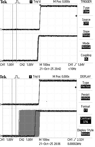
With ±300ns for the PLL plus ±100ns for the GPS1PPS (even though not seen for this short test), we’re at ±400ns jitter and zero drift between the audio sample clocks on two Voter2s! This software+Timer PLL algorithm is working much better than I suspected.
I can think of only two caveats: 1) This is the sample clock. It should be driving the sample/hold amplifiers so reflecting the actual sample time. The clock actually running the A2D conversion is completely free running, but if sampled correctly shouldn’t matter. 2) While it is two fully independent Voter2s each with their own GPS module, I am sharing a single antenna. My lab is in a basement, so I have a shared outdoor antenna and amplified splitter driving my Voter2s.
Back to bug fixes and feature filling. I hopefully get access to a service monitor next week for calibrating.
will