It will take a bit for me to digest your points and discuss with others. I believe we are fully in sync on the need the Voter/ASL path calibration. What you describe is what I’m expecting to be able to do and agree the important part is consistent levels into the server from all nodes.
I would hope that if levels are calibrated for voting they will be calibrated for local mode too. I can see some variations like maybe I have a different mix ratio for voice vs CTCSS or maybe one path has de-emphasis and one does not or something. If it isn’t something inherently correctable, I could see adding a “local mode gain” function if needed.
Also, newbie question: While getting levels accurate for voting is clearly important, it isn’t nearly as critical for local mode is it? You can’t be way off, but ±3dB or even a bit more wouldn’t be terrible would it?
Thanks for the encouragement! The theory on my frequency multiplier and initial testing is looking good, so hopeful. I’m looking forward to getting and sharing some sync traces.
Sounds good, Will. Indeed, there is a lot to digest and discuss there on getting the “right” audio levels.
With respect to adding CTCSS modulation, typically the modulation from the CTCSS source is summed with the transmit audio, and both sources are adjusted independently.
I understand your code changes the “ratio” between the two modulation sources. I’m not sure I’ve seen that implemented that way, and therefore have no experience how that would work. My initial thoughts are that I don’t know if you have the granularity in 1% steps to adjust the ratio to get the levels “right”, and the CTCSS level shouldn’t change… it should be a fixed level.
Typically, you would set the CTCSS level to 500-750Hz deviation (for a 25kHz wideband channel, with a maximum system deviation of 5kHz) with no other modulation present. It is common to target around 600Hz deviation. Apparently, the TIA/EIA RS-220 specification recommended 15% of rated system deviation (15% of 5kHz is 750Hz), but that’s from circa 1979. There is also ANSI/TIA-603-E that calls for 500Hz CTCSS deviation on a wideband channel.
More things to think about.
As for modulation in “local mode”, well, you need to be sure that you transmitter deviation doesn’t exceed the maximum system deviation, or you will cause adjacent channel interference. I could see a 3dB change causing issues. Local mode should just copy the audio samples from the receive chain to the transmit chain, instead of trying to send them though the non-existent host that is offline. That is why you’d have all the level setting on the VOTER2. You calibrate the receive level with 1kHz modulation at 3kHz deviation to the target value, then you’d adjust the level setting on the TX chain to get 3kHz deviation out of the transmitter. Then, if the ASL host disappears and audio is looped, the levels are already set.
Bit of a delay replying to you as I’ve been doing lots of thinking and discussing!
On audio levels, you note the system spec that calls out for a given deviation there should be some # of full scale digital range and that must be universally consistent. Fully agree and it completely makes sense. Between deviation and digital range is the analog voltage between the MTR and Voter2. We just need to agree on what that p-p voltage is for that deviation/%full scale. For the Voter2-2K it can be fixed as the Voter2-2K is for the MTR-2000 only. For the standalone version the Voter2-SA will need to be more flexible given I doubt all repeaters agree on a single analog voltage range. Having that voltage specified makes it easy to know which device needs adjusting if things are off.
A question:
For that deviation, what is the digital range, I assume it is something less than 100% (0-4096 for a 12-bit ADC. That is something I need to use for calibration.
The same applies for Tx audio, for that same given digital range there is a spec on what deviation that should result in (it is hopefully the same as the Rx path). Again, I just need to come up with an analog p-p voltage that ties into that spec so we have that calibration point between the Voter2 and MTR.
I understand now the levels calibration is unity just for 1KHz. Filters, especially emphasis and deemphasis vary by frequency, so saying unity is at 1KHz only is the needed reference point.
On CTCSS in local mode, that is my concern (overflows/clipping). If the setup is that for full deviation we are close to the max ADC range (kinda want that for best fidelity), then when you add CTCSS tones you might end up with overflows and clipping. That is why my code attenuates the voice audio by whatever scale the CTCSS tone amplitude is. That way you are guaranteed by design there can’t be any overflow/clipping. For example if the CTCSS tone is 10%, the audio is attenuated by 10%. That breaks unity gain for the passband audio though. Can’t have it both ways.
Another question:
Chan_voter must be dealing with the same issue (it’s the same math and same restrictions). Do you know how it deals with this for adding CTCSS to voted audio?
After a week of chasing my tail trying to figure out why I broke my RTCM+Voter2 setup I finally got it working today! Note to self: Do NOT use the same client password for two nodes! Yea, newbie error.
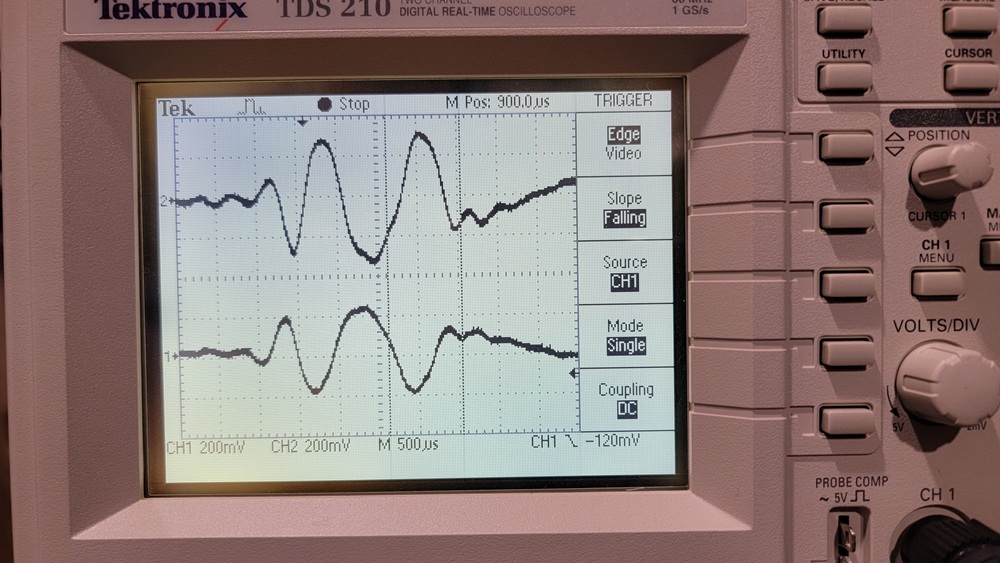
First the easy issue I found: I have the Voter2 send out a test pattern, basically a pulse I send out periodically, and look at the audio outputs of an RTCM and my Voter2 simultaneously on a scope. We have a slight disagreement on where “0” is, but after adjusting for that, here is what I see.
The Nyquist filters (and maybe even the ASL server) generate some artifacts, but they generally match EXCEPT they are inverted from each other! Yep, sure enough I looked at the schematics and I use a non-inverting amplifier on the DAC output and the RTCM/Voter has an inverting amplifier. Missed that. I’m going to declare that an issue to fix in software.
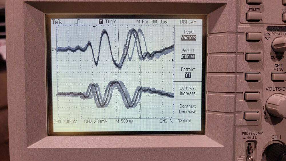
The second issue is a bigger deal and one I feared might be the case. In my case I have a PLL for sample clock. For the RTCM/Voter the sample clock is free-running and it counts samples per GPS 1PPS and adds/deletes a sample to keep it at exactly 8000 samples per 1PPS. That generates jitter of up to 1 sample and I see that in the infinite persistence plot below. I can see the sample getting added/deleted in the top trace for the RTCM. I’m triggering on that as the reference. As such, my Voter2 trace below appears to have jitter too relative to the triggering for the RTCM/Voter. The time between the peaks of the same pulse in the persistence plot is 125us or 1 sample.
(oops, I’m limited to one picture per post, it will be in the next post.)
I’m only superficially familiar with the RTCM/Voter, so more than happy to be told I’m doing something wrong! If so, lemme know. Interoperability with the RTCM is nice, but may not be practical if I’m right. Not a huge deal as there is a good general rule that for a simulcast cell all equipment should be identical and this will include all RTCMs or all Voter2s.
So, when I tuned up a repeater last weekend (Quantar, but that shouldn’t matter). I went and measured the input pin of the ADC in on the VOTER with a scope.
With 1kHz @ 3kHz into the radio receiver (full-quieting), I measured 1.42Vpp at the ADC pin. With a 3.3V reference, that is “roughly” in the middle of it’s range. It too is a 12-bit ADC that it appears gets fudged in firmware to be a 16-bit value (I don’t know exactly how that all works, haven’t looked that close).
The radio under test has a fixed audio output, but not all do, and definitely not all are the same. Hence why the VOTER has a 10-turn pot on the receive line (and the transmit line) to make the necessary audio level adjustments. I expect that the 1.42Vpp at the ADC pin should be a fixed target value with a 1kHz tone @ 3kHz deviation. How you get there (external pots or soft pots) is the challenge.
As for how chan_voter handles CTCSS… it just adds it to the audio stream it encodes. You set the tone and level to a non-zero value in voter.conf to enable it, and measure the deviation on a service monitor listening to the transmitter.
When I tune a repeater with the VOTER, my general process is:
Get the VOTER connected to the host
Send 1kHz @ 3kHz into the repeater receiver from a service monitor
Use Menu 97 in the VOTER, and adjust the RX pot on the VOTER so the bar graph hits the 3kHz mark
Adjust the TX pot on the VOTER so that the recovered TX deviation on the service monitor is 3kHz as well
Turn off the 1kHz modulation and just send carrier into the receiver
Set the CTCSS tone and level in voter.conf (and reload the config as necessary) to get about 500Hz deviation of the CTCSS tone on the transmitter (with the service monitor filters set to <300Hz LPF)
Turn the 1kHz @ 3kHz modulation back on, and confirm the transmitter deviation is now about 3.5kHz (test tone + CTCSS)
Proceed with adjusting the squelch pot to get squelch at the desired level, and possibly adjust the squelch hysteresis to get the desired squelch action
Interesting discovery on the jitter… not sure that one is going to be solvable. Indeed, it may be a known interoperability issue. It would be interesting to hear how it sounds in real life, with the one sample jitter. Of course, you should only hear the artifact when it switches between receivers with different encoders (VOTER2/RTCM)… I think.
And indeed, if you are building a new system, especially trying to do simulcast, everything must be the same. So, it “may” not be a huge problem?
Thanks for taking reference measurements. That really surprises me that the calibration point for Vpp into the ADC is only half its range! That is effectively throwing away a whole bit when you only have 12 to begin with. I would have expected something closer to 75%-90%.
On converting internally to 16-bits, I do the same thing in my code. That way you get max resolution/fidelity for all the DSP routines. That short routine also coverts it from offset (0V=mid scale) to signed (0V at 0) which the DSP routines are expecting. I then convert it back right before the DMAs to the DAC. Well, now I also invert the audio polarity too!
Again, this fixed gain is going to be unique to the Voter2-2K. For the standalone version I will have programmable gain like the Voter/RTCM.
I guess if half the ADC range is thrown away for Rx audio at the start, there is plenty of headroom to add CTCSS without worrying about digital overflows. Just seems wasteful of fidelity.
Newbie question: 3KHz is the max deviation that should be allowed, right? If someone transmits with more deviation, the repeater will do weird things like clip or something, not just send a higher Vpp?
What I can do with my RTCM send a 1KHz tone and adjust the level so that the RTCM display shows 3KHz deviation and spy the IP traffic (decompress it) and see what the digital range is. If there is an easier way, cool, but can at least get the target digital range that way. From your calibration notes above, it should be a digital span of 2048 counts (half of 12-bits).
After a bit more thought, I’m not as pessimistic about Voter/RTCM interop. I’m realizing that all I’ve recently done is “re-discover” that if you want to do simulcast with a Voter/RTCM you need a GPSDO! I’m running it from a regular crystal, so yea it is drifting and the Voter software is correcting as it should. With a GPSDO, that is essentially just another PLL based on 1PPS like what I’m doing in the Voter2 and there should be no drift to correct.
Alas I don’t have a GPSDO, so think I’ve gone as far as I can with the Voter for now. I’m going to “steal” my on-air Voter2 and set it up for a Voter2-Voter2 simulcast test.
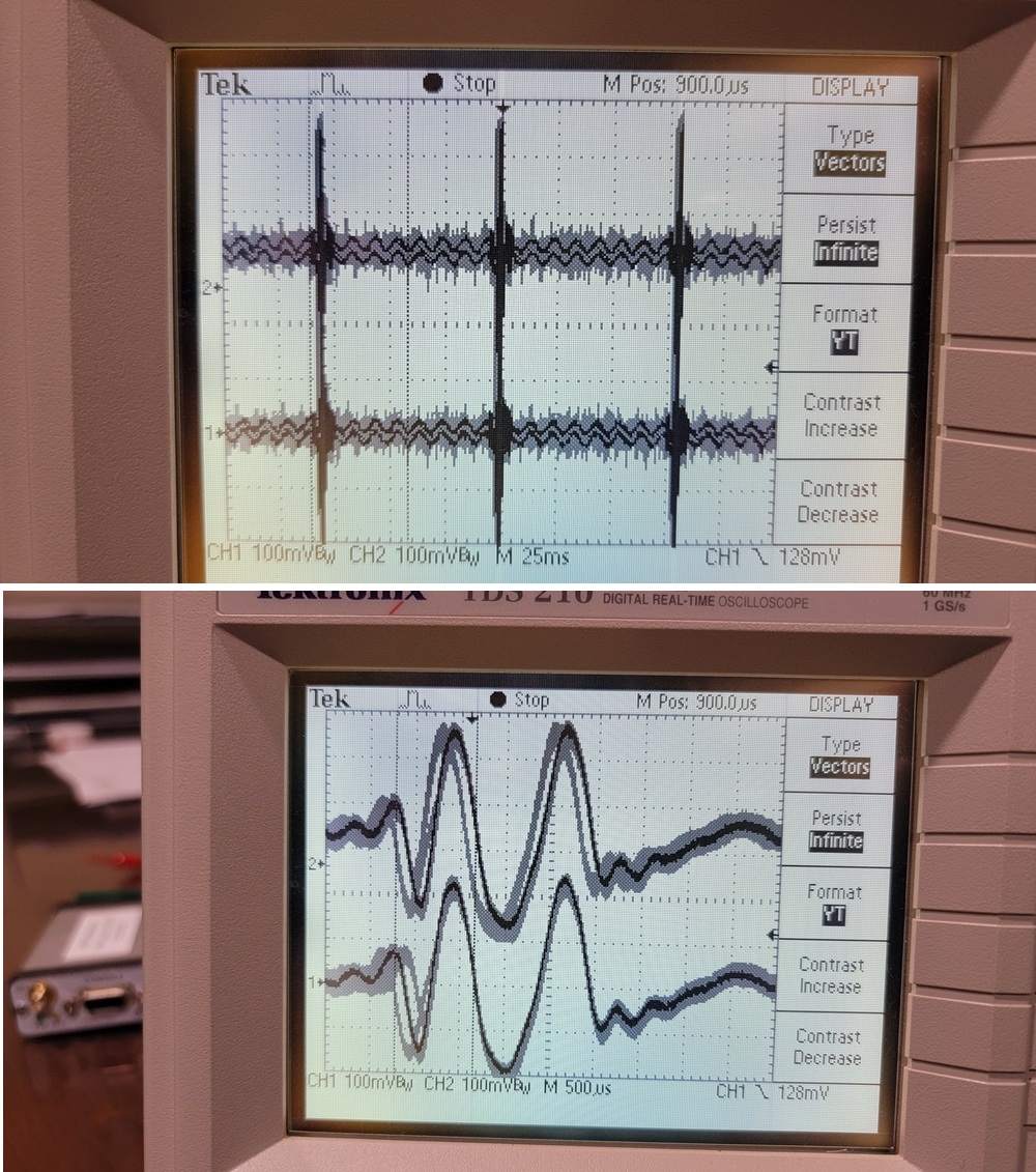
Good news, below is an infinite persistence plot of the audio out of two Voter2s in simulcast mode, each running from their own crystal, GPS receiver, and antenna. The top screen is just to show the pulse positioning, a test mode in the Voter2 generates this pulse every 80ms (4 packets). I have another mode that does a pulse every 11 packets just in case I’m being fooled with an error of exactly 80ms. The lower picture is zoomed in on that pulse. At 500us/div there are about 4 audio samples per division.
As you can see the audio from the two Voter2s are always within 1 audio sample of each other. My current code is only trying to sync up to whole audio samples, so this makes sense. I have a pretty good idea on how to enhance that accuracy to less than an audio sample. While not sure, I feel even if I can’t get better than this, that should be pretty good for simulcast.
With that I am confident I won’t need the 10MHz reference input now, so feeling the hardware design is pretty stable. Back to fixing software bugs and missing features.
will (N0XGA)
p.s. One picture limit? Just combine both pictures into one image! I fully support newbie limits, it protects us all.
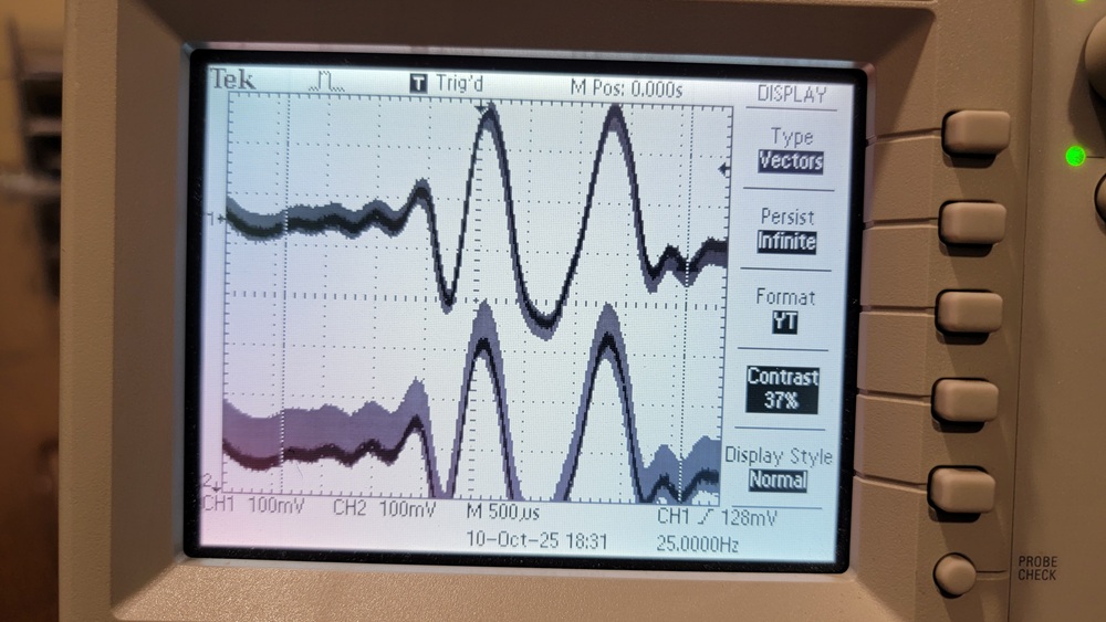
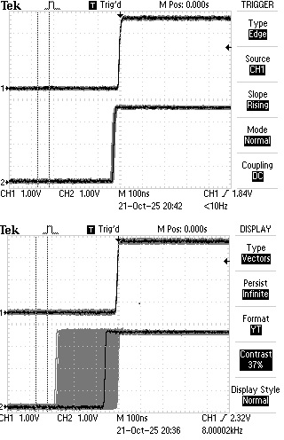
After going back to fix other bugs and missing features for a few days, I went back to spend more time on simulcast sync. Good news! The plot below is between two fully independent Voter2s (same setup as the previous posts) and as you can see now they are pretty much perfectly in sync! That was with the scope in infinite persistence for about two minutes.
The extended grey area on the bottom trace is some DC drifting. That is because I’m looking at the audio outputs which are DC-isolated and I didn’t have a load on the second Voter2s output, so it was drifting over time.
So audio sync between two Voter2s is now fully demonstrable. Sync between a Voter2 and a Voter/RTCM I think is possible, but still a stretch goal. Enough folk (on here and elsewhere) are concerned that even if sync with a Voter/RTCM is possible, the differences in filters and such will lead to other weirdnesses that may not make them compatible.
Sorry I haven’t replied sooner, bit crazy around here right now.
In answer to your questions…
No, 3kHz isn’t the max deviation allowed. That is just the standard test tone deviation level. The actual maximum deviation before limiting is applied should be 5kHz. Above that, typically a limiter circuit is employed to keep the deviation from exceeding that amount, which could lead to adjacent channel interference.
So, while you are only using less than half the ADC range at 3kHz deviation, that is probably not the case at full system deviation. I will put a scope on the ADC pin next time I tune up a radio (probably soon), and see what the level is when the deviation is at 5kHz. It may also change with frequency, depending on de-emphasis… so I will make some measurements at 300Hz and 3kHz audio tones to see what it looks like.
Don’t forget too that we’re dealing with 8kHz, 16-bit (12-bit) audio… so we’re not talking a lot of fidelity to begin with.
If you need/want a 10MHz GPSDO to mess with as a reference, I can hook you up with one, for the cost of shipping. It would be a pull from a CDMA base station, so it needs 48VDC to operate, but it makes a nice 10MHz once it is surveyed in.
OK, thanks for the elaboration on 3KHz deviation. I fully admit while I enjoy the embedded side of things I’m not that well versed in repeater operations/specs. With any luck I’m going to be able to borrow (and get taught how to use) a service monitor in a few weeks which is going to help a lot. While the Voter2 is functional, I know I have a LOT of calibrating to do! Matching RSSI is going to be interesting.
It may be a bit of a stretch, but my assumption/hope is that if the Voter2 can put out extremely well-synchronized audio, that is sufficient to feel it is doing its part for simulcast. The above scope traces hopefully confirm that so I can feel confident the Voter2 doesn’t need a 10MHz GPSDO input. That means other than a few minor tweaks and clean-up items the hardware is good to go.
Oh yea on fidelity! I spent 3-ish days trying to figure out why my ADPCM compressor/decompressor sounded terrible only to find out it was working exactly as it should! After chasing my tail for days I began to wonder, so took my test stream and ran it though Audacity with the same compressor settings and it sounded just as bad. Oh, working as designed.
Dave (WA1JHK) and I do wonder if at some point in the future it may be worthwhile on some future version to go to an external codec and net more bits, higher sample rates, and probably less analog noise off-MCU. While it may improve the fidelity of local repeater operations, I’m pretty sure the limit on sound fidelity while voting is the sample rate and compression. Those aren’t changeable without changing everything.
Oops, forgot to answer your final question! If possible, hold the thought on the GPSDO. It is tempting and I will probably need one eventually. If full interop with RTCM/Voters becomes a real need, then I will see if you still have any available. I’m very space constrained. I’m going to have to temporarily move a lot of stuff to make room for the service monitor!
I can’t tell you how much time I spent on the voter client password duplicate issue years ago… I thought password meant password, but it really means the unique identifier for each client… after I figured that out it worked great… in addition if I remember correctly it either cannot be all numbers or all letters (can’t remember which) so I made mine in the password1 format…
Yea, that cost me almost a week. Newbie error. Big difference for me is since I’m working on the new Voter, I (correctly) initially assumed the issue was with my Voter2 and was chasing down that rabbit hole, not messing up the ASL3 config!
I’m not sure how dynamic and frequently updated the chan_voter code is, but a cool feature request could be to show an alarm if it sees the same password from two different IP addresses. For all I know IP addresses may already be abstracted away by the time it sees data. Safer for me to stick with what I can control, the Voter2!
I’m not sure how dynamic and frequently updated the chan_voter code is, but a cool feature request could be to show an alarm if it sees the same password from two different IP addresses. For all I know IP addresses may already be abstracted away by the time it sees data. Safer for me to stick with what I can control, the Voter2!
I took a break from bug fixes and feature filling (none of it worth posting about) to go back and better measure simulcast sync. I have a way to expose the audio sample clock outside the MCU by stealing one of the less-used debug pins, SWO. Knowing I am in sync down to the sample level, I can focus on just the sample clock, knowing that is the total jitter.
Below are two infinite persistence plots at 100ns/div, the top one is the two GPS1PPS signals on two different boards over about two minutes. The jitter there is scary low, barely a few pixels. Over a few minutes that isn’t unusual. I’ve run two GPSes overnight and seen ±100ns which I think is a bit more normal. Below that are the audio sample clocks on the two different boards. I’ll round up to say -300ns to 0ns. Not visible in the snapshot was the actual edge progresses right to left then “resets”. This is highly likely due to different local crystal frequencies with one being faster or slower. Grumpily I could see if the crystal frequency difference were opposite, maybe the drift could be +0 to +300ns.
With ±300ns for the PLL plus ±100ns for the GPS1PPS (even though not seen for this short test), we’re at ±400ns jitter and zero drift between the audio sample clocks on two Voter2s! This software+Timer PLL algorithm is working much better than I suspected.
I can think of only two caveats: 1) This is the sample clock. It should be driving the sample/hold amplifiers so reflecting the actual sample time. The clock actually running the A2D conversion is completely free running, but if sampled correctly shouldn’t matter. 2) While it is two fully independent Voter2s each with their own GPS module, I am sharing a single antenna. My lab is in a basement, so I have a shared outdoor antenna and amplified splitter driving my Voter2s.
Back to bug fixes and feature filling. I hopefully get access to a service monitor next week for calibrating.
A query from an interested ham made me realize that I’ve been a bit too quiet about the Voter2 status. Progress has been good, but some “life getting in the way” has slowed things down more than I predicted. Good life events at least, but still big time consumers. The progress recently:
I am phase 1 feature complete except for calibration support, both levels (which is hardware too) and RSSI. Yes, there are bugs I know about and many I don’t yet! Analog RSSI from the MTR-2000 is easy, but I also want to match as closely as I can the “above band” RSSI calculation computed by the Voter/RTCM. That is going to take a lot of tweaking. Both RSSI efforts require…
I finally have been able to borrow a service monitor! I’ve been trained on the basics and tinkered with it a bit and see the basics working with the Voter2. First, however I need to go through an RTCM calibration process to measure some important parameters so I can ensure the Voter2 behaves similarly. I’ve never gone through that on an RTCM before, so it is a bit of a learning curve.
Dave (WA1JHK) and I are discussing some final nice-to-have tweaks to the schematics and layout for what we hope will be the first small production run of boards. The tweaks are pretty minor except for…
We think we can cost effectively add a 10MHz reference good enough for the MTR-2000 to do simulcast. It is far from certain, but the theory is good. This first board won’t support it (we have to prototype it and evaluate it), but to ensure we don’t orphan any earlier boards, we need to change the MCUs crystal from 25MHz to 10MHz. This isn’t a big deal as the MCU has PLLs that can adjust to the new clock and still get all the same internal frequencies. I don’t want to support two crystal frequencies “forever”, so making this change now.
To emphasize, the first production version of the Voter2 will still support simulcasting. It won’t need the 10MHz reference, but the MTR2000 still will. If this new idea works, then the Voter2 will provide the 10MHz to the repeater instead of needing an external one.