Announcing the Voter2!

Allstar Community folk:

After over a year of development (and not done!), I am pleased to announce the Voter2. There is more detail below, but I wanted to begin with the major “headlines” right up front:

- It is fully open-source hardware

- It is fully open-source software

- It is fully compatible with and interoperable with ASL1, ASL3, and Voter/RTCMs.

- It is a ground-up new design using modern silicon

- It has on-board GPS support

The gate for announcing the Voter2 was actually getting one on the air, not just a sandboxed test setup. A Voter2 is now on the air on an experimental repeater for the Colorado Connection—one of the project’s sponsors.

The only major feature not fully coded up is simulcast support. The hardware should be capable, and initial coding is complete to get to sample-level accuracy, not sub-sample yet. Testing/debugging is involved and will take time. Simulcast interoperability will only be between Voter2’s initially in keeping with the “keep the hardware identical for Simulcast” philosophy. Interoperability with Voters is a stretch goal. Outside that there are still things like analog levels and RSSI calibration that need doing as well as many special case features in the Voter that to be honest I need to better understand before even being sure how to support them.

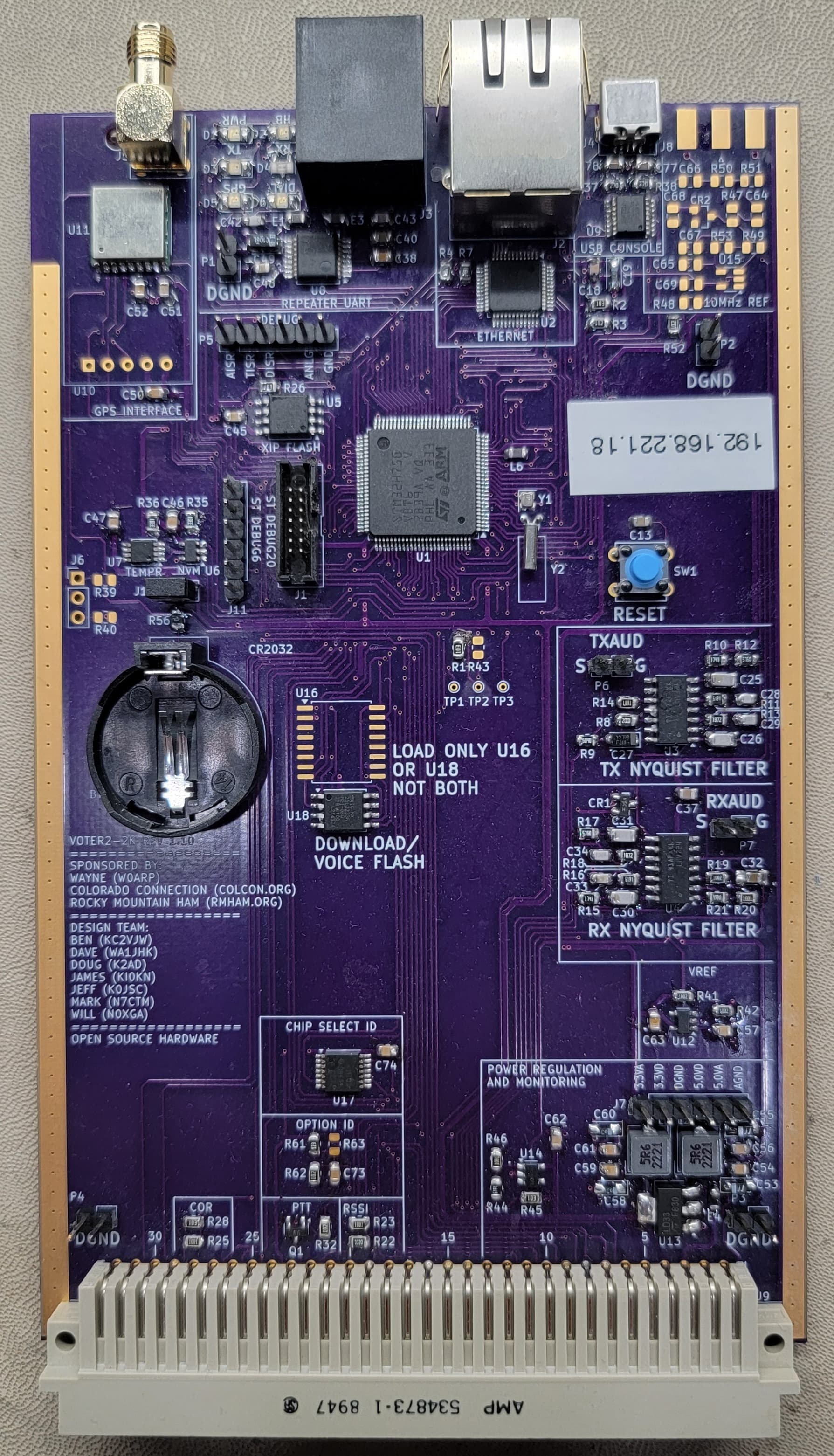
The first physical version of the Voter2 is a plug-in card for the Motorola MTR-2000 repeater. The sponsors really wanted something with fewer wires and “things to go wrong”. There will be a standalone version coming for more general-purpose use. The plan is to see simulcast working to be confident that we have the right hardware before making the standalone version.

The Voter2 project concept began many years ago, but started in earnest during our panic when RTCM production stopped. The Colorado Connection has an 18-repeater network using them. RTCMs are back in production, but the project continued, just not as panicky!

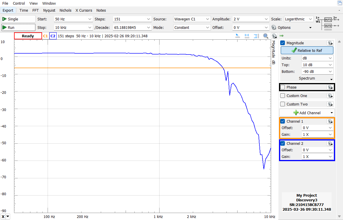
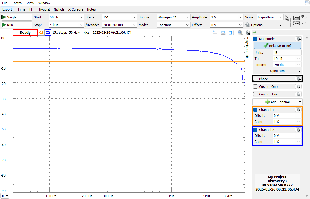
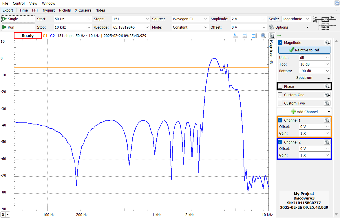
Besides the headline features noted above, the other big feature is expandability. The Voter2 is based on an STM32 Cortex M7 MCU, the STM32H750. It has over 1,000 DMIPS and paired with 1MByte of RAM and a bit over 4MBytes of flash. The baseline feature set is using 10% or less of each of those resources, so ready for the future. The only analog filters are Nyquist filters for Rx and TX audio. All other audio filtering is DSP based.

The Voter2 makes use of two big open-source projects, FreeRTOS and LwIP. While I have no illusions that the current state of the Voter2 is as reliable and bullet-proof as the Voter/RTCM, using these projects provides a good foundation. FreeRTOS will allow much more structured and maintainable code and LwIP provides a robust IP interface.

There are directories for each hardware and firmware revision. Each hardware directory has the KiCAD design files and its paired hardware reference manual. Each firmware directory will have the STM32CubeIDE project tree and paired software users guide. The DUT board directory is only if you want to do development work without using a repeater, and finally the Other Docs directory is for other supporting documentation not tied to a specific hardware or firmware revision. There are no known hardware issues, but I do plan on one more board spin to clean things up a bit.

Do note that while the Voter2 is fully compatible and interoperable with the Voter/RTCM, that is for the protocol. The UI is quite different, it is command line based versus menu based. This allows better feature expansion and segmentation.

The Voter2 does have one neat feature above the baseline Voter/RTCM. It supports a subset of the RFC2217 “UART over Telnet” protocol that allows you to remotely configure the MTR-2000 over Ethernet. This actually works with the ancient Motorola RSS software! Setting up the drivers on 32-bit Windows XP is a bit tricky (details are in the Firmware Users guide), but do work and MUCH easier than a site visit. I suspect there are better drivers with easier setup, but the feature at least works.

In addition to being fully open-source, Dave Maciorowski, WA1JHK, of SCOM and JHK Labs (https://jhk-labs.com) also plans on offering ready-built and tested Voter2s if you prefer not to build one yourself. He is a core part of the development team. The reality of any non-trivial silicon for the past decade is that we are stuck with surface-mount parts and this board reflects that. In addition to Voter2s, Dave is also is porting a version of the 7330 controller firmware to a modified Voter2 platform called the 7110e that will clearly not be open source. Here’s a video that introduces the products that Dave showed at Hamvention 2025: https://www.youtube.com/watch?v=8kUs3bc9kRM

On timeframe, getting on the air was a major step. Voting works in a sandbox environment, but yet to be confirmed “in the wild”. Multiply that by 10 for real-world simulcast testing. Initially, the Voter2 will definitely NOT be as robust as the Voter/RTCM which has millions of on-air hours. There will be bugs and “errors of assumption” to iron out over the next months. If simulcast isn’t a need, then I could see some early adopters trying out Voter2 by the end of this year or early next year.

On the build-it-yourself cost, the “Quantity 10-ish” pricing based on DigiKey and a US PCB supplier is about $125 (plus taxes, tariffs, and shipping). A costed BOM with DigiKey part numbers is in the KiCAD directory. Much cheaper PCBs can be sourced from China (JLCPCB in particular), and DigiKey’s fame is reliable sourcing and quality more than lowest cost.

will (N0XGA)

1 Like

As a newbie, there is a restriction on links per post (a fine restriction), so I had to omit the github link to the project. Here it is GitHub - beals5/Voter2-2K: Voter2-2K design files. That is all files for schematics, PCBs, software, and user guides.

Also, below is a picture of the board, a plug-in card for the Motorola MTR-2000. The connectors along the top are GPS, RSS (to talk to the repeater), Ethernet, and USB-UART. The empty area on the right is for a 10MHz reference for simulcast that I hope to not need anymore.

will

1 Like

Hi Will,

Wow, that’s a pretty tremendous feat, if you’ve got one on the air and talking to an ASL host. :slight_smile:

I know it has been on the wish list for a very long time to port the code to something with more code space, so hats off to you and your team for taking on that challenge!

I’ve had a cursory look at your documentation/schematics, and have a couple of comments so far…

I agree with the choice to have the option to use a quick off the shelf GPS module. I use the same modules, and they get the job done. I will note though that you might want to consider on your next board rev to feed the module 5V instead of 3V3. I believe those boards will take the 5V and feed it to the antenna connector, and they have an on-board regulator to feed the GPS chip with 3V3. That helps for longer coax runs, and not all active antennas work with 3V3. Something else to consider (more for simulcast) is that there are surplus uBlox M8T modules available that are tailored for timing applications (and do multi-GNSS)… but they use a different form factor.

Regarding 10MHz… I would still leave 10MHz support on your road map to fully implement. In a simulcast scenario, you are very likely to have 10MHz from a GPSDO already available (synching the transmitter). I know on many of our commercial wireless networks, PPS isn’t/wasn’t enough to synch everything… we still used 10MHz, 9.8304MHz, T1/E1 BITS, etc.

Looking at your hardware block diagram, I see you’re doing de-emphasis of the receive audio, but if you drop into “local mode”, don’t you need to pre-emphasize the transmit audio (currently un-implemented)? Perhaps not, depending on how you configure the MTR-2000… but in a “generic” implementation, this would be an important feature.

I’m looking forward to further firmware updates, and getting simulcast working. I was going to spin up another set of original boards to stuff in my Quantars… but now I might have to change horses and try out your design instead. :slight_smile:

I also think there is definitely a market for an updated platform version, in a more generic package, which shouldn’t be too difficult since you’ve already done all the hard work!

Good job!

Lee

2 Likes

Thanks for the kind remarks Lee!

It has been a fun journey so far–and far from done! I am very impressed that Jim designed something that is still fully manufacturable today as it was ten years ago. I’m definitely striving for the same thing. The Ublox module is the “now” solution that I fear is not 10-year solution, hence wanting something from a reliable long-term source for the long term solution, the TESO module. I can certainly look at selectable voltages.

The 10MHz input is there as that was the initial intent for simulcast. Dave (WA1JHK) and I had a big “oh crud” moment on an RTCM compatibility issue that forced me to look a lot more closely at sample clock generating and I’ve managed to code up a software/Timer PLL (well frequency multiplier really) that is giving me an incredibly stable audio sample clock phase locked to the 1PPS. I’m getting jitter less than 250ns relative to 1PPS with zero drift since its phase locked. If it is really that good, then yay! But, proof is in results, so the circuitry stays until proven it isn’t needed. Fully understand 10MHz is still needed for the repeater, so can’t get rid of it completely.

I agree I’m probably off on the logic of preemphasis and deemphasis in modes. Those are the important things I need to get educated on by real repeater experts. Messing it up more is I have that DUT board that just feeds raw microphone audio into the Voter2! I know there are lots of important things like that I’m overlooking. Functional is good, but details get you to the useful product!

I am committed to a “stand alone” version of the Voter2 for sure. It will clearly be very similar to the Voter2-2K, I’m extremely confident it can share the same source files, just with #defines for the differences.

will (N0XGA)

In regards to all the pre-emphasis/de-emphasis stuff, I did some testing a few years ago, you can see how the VOTER and Host interact here: VOTER Audio Analysis - AllStarLink Manual

As a side note, I expect your DSP filtering will probably have more precise results than the hardware (as evidenced by the sweeps on the referenced page). In the real world, that would probably have an effect if you tried mixing VOTER and VOTER2 in the same system (since the audio response would be slightly different).

As for the “stand alone” version, I don’t know if there is a whole lot of code you would need to comment out. Sure, most folks probably wouldn’t need things like the SPI interface, but it doesn’t hurt to leave it enabled… less firmware versions to manage.

Do you have another hardware revision in the pipeline, or is this going to be the initial release candidate? The reason I ask is that if this is going to be the one you’re going to run with, I might look at building a few to poke around with… if there is another release coming, I’ll hold off.

I’m curious to see how well the in-band squelch works in your code with the Quantar (aka Jim’s “BEW” solution for radios with no high frequency audio).

I think I know what I might be working on this winter…

Lee

1 Like

Lee:

Oooh, those are some good plots to take a look at for comparison purposes! I have similar plots for my Nyquist analog filters and even have a nice way to get plots of my digital filters (see the probe command) using a Digilent Module Dave (WA1JHK) recommended. I’ll find a way to upload those plots somewhere.

For the standalone version it won’t be hard to #define out things not present. The bigger effort will be support for programmable input/output levels since I didn’t have to bother when targeting only one repeater. I expect a spirited debate on that level setting being digital vs mechanical pots. I can see both sides of the argument.

I maybe have one hardware revision coming, but just for some minor footprint issues for which I have decent workarounds. Hence the “maybe”. Dave and I are discussing a major revision aimed solely at manufactureability. Ideally not a single schematic change, but a completely new layout optimized for JLCPCB design rules. No SMT parts on the bottom side saves a lot of cost.

Above is a far cry from the Rev 1.0 to Rev 1.1 change. I messed up what was supposed to be a simple edit and was “off by one” on the entire 96-pin backplane connector! That was embarrassing.

I am expecting a lot of tweaking will be necessary when it comes to RSSI. I have access to the MTRs analog RSSI level as well as a nice sharp DSP high pass filter for upper band sensing. It should be a good foundation, but know it will be a lot of tweaking to get similar to the Voter. Your plots will help me get closer. I’m working on getting access to a service monitor for that work.

will (N0XGA)

Lee (and all):

OK, I’m going to try and post some of the frequency plots. These were taken with a Digilent probe set up to do spectrum scanning where it sweeps a frequency on an output and shows the amplitude of the response. Given there is a lot of DSP in between, there are a few artifacts here and there, especially around the Voters Nyquist frequency.

Nyquist filter (scanned out to 10KHz): Seems OK for a 4th order filter, again a bit of weirdness around the 4KHz sampling frequency as I’m sampling the ADC output. I don’t want this cutoff too steep as I want some frequencies–even if aliased coming through for the high-band RSSI calculations.

Oops, I had four more plots, but us newbies are limited to one per post! :slight_smile:

will (N0XGA)

Hi Will,

Actually, I was just going to ask about level setting. I note in the block diagram that TX/RX level setting is shown, but there is nothing on the schematic to effect that, nor any mention of level setting commands/procedures in the software manual.

That’s definitely going to have to be something that needs addressing, and you might even find it suitable for fine-tuning the adjustments in the MTR-2k.

Software or hardware doesn’t really matter. The VOTER uses hardware (pot) to calibrate a standard test tone into the receiver to a known level (using a software bargraph), and then uses a hardware (pot) to set the transmitter deviation. It is critical to align all the receiver audio levels to be the same, so you don’t hear level changes when you switch receiver sites. I don’t see how that works with this design.

On the other hand, channel drivers like simpleUSB and USBradio do all the level setting in software (setting the mixer levels). Again, using a bargraph to first setup the receive level to a consistent value, then adjusting the transmit for proper deviation. This ensures the receive audio level going into the network (ASL) is consistent, so that (when properly set) all nodes sound about the same level (so you aren’t always having to fiddle with the volume control every time a different node is received).

So, either way is fine. Software may (?) be easier than adding more hardware to the board, and designing access to the pots.

But, at the end of the day, being able to calibrate the audio levels to known and repeatable levels is important.

On a similar topic, I didn’t see any provisions to adjust squelch level and (optionally) hysteresis. I know you are calculating RSSI or experimentally using the analog RSSI line from the MTR-2k, but how do you adjust the squelch threshold?

Lee

Lee (and all):

For now a series of short posts with plots given the temporary limitation of one “media item” per post:

Deemphasis in the voice band:

High pass filter for RSSI calculations:

Again, for this filter I don’t mind the passband going beyond the Nyquist frequency a bit. It just folds back so energy above 4KHz will still be counted as long as it doesn’t fold back lower than 2.4KHz.

Voice-only filter (omitting CTCSS and above 2.4KHz).

Also, just to emphasize, this is MEASURED response using the Digilent device, not theoretical plots from the filter generator. Those look much nicer! :slight_smile:

The nice part is other than Nyquist filtering (which is pretty solid), the rest of these filters are all “Just software” and can be changed if I needed!

will (N0XGA)

I'll be curious about that, too. Our group and friends are mostly running Motorola Quantar repeaters with RTCMs attached. The discriminator output from those is digitally processed and, as Lee mentioned, there is little high frequency noise unlike a real discriminator output. This mainly impacted RSSI for voting but there may be some role in squelch operation as well. BTW, the RTCM squelch operation is a thing of beauty, very fast and MICOR like.

Jim and friend created what he called BEW or Bandwidth Elimination Window. I believe the basic idea is BEW attempts to look between voice peaks for noise.

1 Like

WD6AWP:

I’m at least as curious as you! :slight_smile: Plan A for the Voter2-2K is to try to use the analog RSSI output from the MTR-2000. Its iffy, but if good by far the simplest. As you can see above I do have the “above band” audio filter set and getting raw data from it and it is at least functional, but I haven’t yet tried calibrating it. I have a status command that shows a waterfall-ish display of both the analog and above-band RSSI values live. I do see the above-band RSSI bouncing more than I’d like, so know it does need some tuning still.

My code is pretty modular and I have dedicated functions for the two RSSI algorithms now and fully expect there will be more coming Other than knowing the “BEW” algorithm exists, I don’t yet know anything about it. If it can be implemented on the Voter/RTCM, it should be possible on the Voter2 too.

will (N0XGA)

So, the "Micor” squelch is implemented in squelch.c:

As for the calculating the RSSI using in-band audio, the main routine for that should be:

And, it appears that Jim was calculating energy from 300-2000Hz (if the comments are correct, I’m not a DSP guy).

2 Likes

@ve7fet :

Thanks for the squelch code snippets. Hopefully I’ll be getting to that soon. My short term priority is getting enough confidence in simulcast support that I can declare the hardware good and start building some more Voter2s.

I realized this past week that the three Voter2s I made isn’t enough! I have one for development, one full time in a repeater in my basement connected to the Colorado Connection Voter network for long term testing, and the third with Dave (WA1JHK). To do simulcast testing I need one more and another to soon go to a “real” repeater site for more rigorous testing. In the short term I’m doing simulcast testing with an RTCM.

Testing last night went well. My Voter2 and the RTCM seem to have a difference of opinion where “0” is for delays which isn’t surprising. There are a lot of assumptions that go into that, so can adjust as needed, but once adjusted manually, it looked not too bad. One device had CTCSS enabled, messing up scope triggering. Today, however, I broke something and now all ASL audio is garbled–OOPS! I’ll fix that soon and post a plot when I can.

will (N0XGA)

@ve7fet

Hmm, looking more at your comment after the in-band audio RSSI value, that does seem awful strange. It was my understanding that RSSI was calculated by looking at energy ABOVE the audio band. That is, “legitimate” audio is limited to no more than 2.4KHz, but the discriminator can detect upwards of 4KHz. The only way there can be any energy above 2.4KHz is if it is noise. Hence the lower the noise above 2.4KHz, the stronger the RSSI.

That is what my code is attempting to do. If incorrect, then it clearly needs changing! Between your post and the earlier ones I think I have all the info I need to better understand how it is supposed to work.

will (N0XGA)

Yeah, I don’t know if the comments in the code are accurate. In the non-BEW code, it is my understanding that the noise above 3kHz (or wherever) is used to determine RSSI. I don’t know enough about DSP to determine how it is done in the BEW code.

Good to hear testing is going well.

I asked before, but maybe you missed it… how do you calibrate the receive audio level, such that a known audio level is sent to Asterisk when a standard test tone (ie 1Khz@3kHz) is sent into the receiver?

On the subject of boards, I loaded up the project in KiCad, but it was very unhappy when I ran the DRC on the board because it was missing your custom parts library with custom footprints. Can you include your library in your repo files, and/or include the Gerber files for sending to manufacturing?

Cheers!

Lee

Lee:

Oh! I thought one of the major enhancements with KiCAD 6 or 7 was that they copied the necessary library parts into the design file so you didn’t need to include libraries anymore. Guess not or its not automatic and I didn’t flip that bit somewhere. Easy solution for now is to upload my library and its there now in the board directory. Alas I started another PCB design yesterday so just upgraded from V7 to V9 and my library got updated. Good thing I have backups! :slight_smile:

Sorry about forgetting to answer on audio levels calibration. Again, here is where I’m not an expert on the repeater, but the experts I’m listening too say for the MTR-2000 as long as I have something roughly good on the Voter2 side, any levels fine tuning can be done on the MTR side since it is programmable. No need to do it on both sides. That will not be the case for the standalone Voter2 where that may not be possible on all repeaters. That I think is going to be the big difference between the two. Besides the green/yellow/red audio level LED I also have a waterfall-like bar meter for audio levels (status level) that also gives a 0-255 integer output. Hopefully that is a good start at least.

For Tx I also have a test tone command (ttone) that lets you send out a test tone of any reasonable frequency and the level can be in % of full DAC scale or raw DAC range.

Again, I’m fully expecting there to be lots of implementation details I’m missing! The first round of feedback from someone besides me actually using the Voter2 is going to be lengthy! :slight_smile:

will (N0XGA)

Yeah, I was trying to do the DRC in KiCad 9… I will try again.

Here is a relevant thread on what ASL is (may) be expecting to see for audio levels: USBRadio audio crackling (s16 overflow distortion) and other audio issues · Issue #791 · AllStarLink/app_rpt · GitHub

I understand that you can tweak the MTR-2k externally for RX level and TX level. That’s all fine and great if you are on a closed system (maybe), and no other ASL nodes connect to you. You’re experts may be missing a big and important part of the whole audio level discussion… the audio level you are sending to everyone that connects to you.

Let’s consider the RX audio path primarily, as that is the critical path to the discussion.

Audio comes in on RF to the receiver and gets sent to the VOTER2, through the Nyquist filter, and into the A2D. From there, it goes through some filtering, then SPLITS. Actually, that’s not even completely true, because it splits twice, as we will see.

In the first split, you go to “Compression” and “Local Mode” (which may be an incorrect implementation… it may need to be done in “Packet Processing”, see below), but there is actually a second split in the ASL host (after you compress/process the packets and send them to chan_voter in ASL).

On the ASL host, the audio gets routed two ways. First, it gets looped back to the associated repeater transmitter(s) (back to the VOTER2 for TX processing). Second, it gets sent to the network, which distributes it to any other attached nodes connected via the ASL Network (or direct to any other “Private” nodes, as the case may be).

And this is where we run into the calibration issue. It is imperative that the level of incoming audio packets TO the ASL host be of a standard level, so that when they are sent out to any nodes on the network, they get transmitted at the same standard (volume/deviation) level.

As noted in the link above, when a full-quieting 1kHz tone at 3kHz deviation is applied to the RF input of the receiver, the “waterfall display” in the channel drivers should hit column 34, which should result in an audio sample with a level of 7427 / 32767. I think in your case that would be 928/4096 (in which case, when you turn the RX LED to green at 1024, your audio is already too hot)?

This sets the calibrated value that is sent into the “network” for all other nodes to transmit, as well as that same level will be sent back to the local transmitter(s).

Now, on the local/VOTER side, you have this standard level being sent from the ASL host, which you would then use any level adjustments in the TX audio path (either on the VOTER2, or in the MTR-2k itself) to adjust the corresponding transmitter to deviate to 3kHz.

That’s also way I say I am not sure you are peeling off the audio for “local mode” in the right place (haven’t looked into the code, you’d know better than I). You would want to pick the audio off at the same place you would normally be sending it to the host to loop it back (since the host is unavailable). This would ensure that the audio you loop back in local mode is of a calibrated value, so the audio level (deviation) of the transmitter doesn’t change when you toggle between local and network modes.

So, I would disagree with your “experts” that as long as the levels are “roughly good”, they can compensate in the MTR-2k. That is incorrect. The receive level is a critical level to set, as it affects everything that is attached. In fact it would affect your own local system too, since if you have multiple voted receivers, and they are all not set to the same precise calibrated level, every time the ASL host switches to a different receive audio stream (based on RSSI), you’ll hear the audio level change.

On the ASL channel drivers, and on the original VOTER, you have a waterfall display that looks something like (it’s going to render poorly here):

RX VOICE DISPLAY:
=================================v -- 3KHz v -- 5KHz
|================================>

When you adjust the receiver’s level into the VOTER with a 1kHz tone at 3kHz deviation, your goal is to get the tip of the arrow on the lower bar to hit the 3kHz arrow (which should be column 34).

When you do that to each receiver in the system, they are all calibrated the same, and you won’t hear any perceptible change in audio level when the system switches between receivers.

How do you test this, and see if the VOTER2 is behaving as expected? Well a simple way is to connect to a non-VOTER repeater that has been configured/calibrated using one of the other channel drivers (chan_simpleusb or chan_usbradio). Then, when you send 1kHz @ 3kHz into the VOTER2’s receiver, it should come out on the other node at 1kHz @ 3kHz too. If the deviation is not the same, then your receive level in the VOTER2 is not correct.

Lee

This is the most exciting thing i’ve read in a while. As an owner with a 5 site (soon to be 6 site) MTR-2000 RTCM based simulcast system, I’ve been looking for a replacement to the old boxes. If we can eliminate the 9.6mhz deal which it looks like we will, it will greatly improve the crossover issues we experience with the current RTCM’s

1 Like