The purpose of this post is 2 fold.
-
To provide all the general information I have at this time to the topic in the hopes that those interested in it will band together and will do something with it. Just trying to speed you up?
-
To some of those same folks, to stop them from asking me by email and PM’s the same and proposing I do something as I am not interested and repeating much of the same info I’m putting here… I have plenty of irons in the fire. So I will refer this post when asked in the future.
It’s up to those of you interested to do something. Work together perhaps in a new thread for discussion.
Personally, I might try something myself of utilizing the entire GPIO string much like we do on a PC with a parallel port. (I believe it can be done) But not now for me.
So,
Here is most of what I know, but let me start with what I believe to be true…
Someone please fill us in with corrected or additional data.
It looks like The Dude (Jim Dixon), before he passed was working on this and looks to be almost finished or unfinished before his unfortunate bad health and passing.
What part is unfinished?
Well we don’t have the hardware part now do we? More? We don’t have complete examples of the config’s. Or do we? Glancing at the code, it looks like it is all there but does it work bug free?
I have not asked DMK folks what their story is on this, but perhaps they will notice and put in what they can tell us. Or one of you could ask and tell everyone here.
About what we see in software…
There is a module required for the channel driver that must be enabled
chan_pi.so
(this is used much the same as chan_usbradio.so)
And you have pi.conf in /etc/asterisk
along with similar config files for this Pi interface channel driver.
From the source code I will post at the end, one can determine at least some of the following.
COR and PTT are accessed via a I2C interface on the Pi and addressed accordingly.
And the default address is 0x27 for that I2C device and some iface driver file for it located /dev/i2c-1
You have a maximum of 2 nodes that can be described and addressed for CTCSS, COS & PTT.
These 2 possible nodes are shown in the example configs as 1 & 2 (simple right).
Named not by node number as in simpleusb or usbradio. But 1 or 2.
If you read the various config files, you will learn more about this.
I think this is missing from the start of the pi.conf
i2caddr = 0x55 …but without it, the default 0x27 prevails.
The software is expecting ALSA sound drivers. So that will need to be enabled as well in modules.conf, but what exactly? The built in sound using left and right channels?
I did not look that far.
But there is a reason you can only define 2 nodes. So, I am assuming a bit.
What to use for the I2C Parallel Expansion ?
I can only ‘guess’ that something like this would do the job.
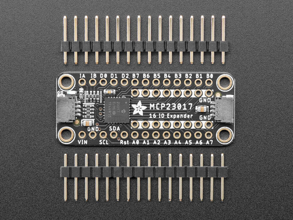
…
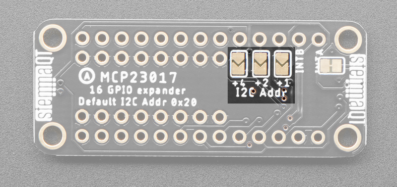
The base address of this animal is 0x20 without jumpers.
and with these jumpers, you can change that to 0x21- with all 3 of them jumpered 0x27.
But if someone were to try some other device and not be in range, I think you could set that in the config file as I mentioned before.
Full specs on the device I mentioned above are here
One can achieve 3.3vdc +/- from the pins on the Pi header
+3.3Vdc = pin1
- ground = pin39

pin 3 = Serial Data (sda)
pin 5 = Serial Clock (scl)
So, that’s all 4 pins needed in a row on a pi3 /b+
First the Pi i2c interface must be enabled.
raspi-config > interfacing options > i2c enable/disable > yes
No reboot required
look in /dev for i2c-1
If you insist on a quick test…
lsmod | grep i2c
or
raspi-config nonint get_i2c
good to go
You will likely need some tools to play with an i2c
i2c-tools
While it may be in the apt repo
apt-get install i2c-tools
Only with any issues with this, then do a manual install and download the latest
https://mirrors.edge.kernel.org/pub/software/utils/i2c-tools/
unzip/untar to a directory in /tmp
enter that directory and run the following
make uninstall
make clean
make USE_STATIC_LIB=1
make install
to test the tools and your board
i2cdetect -V
will give you the version of the software and you know it went well.
i2cdetect -l
should return a line that looks like this
i2c-1 i2c 0b234500.i2c-bus I2C adapter
^ the i2c-1 above shows us it is dev 1 as it is in /dev/i2c-1
then a command of
i2cdetect -y 1
will show us the addresses of all the board(s)
     0  1  2  3  4  5  6  7  8  9  a  b  c  d  e  f
00:                         -- -- -- -- -- -- -- --
10: -- -- -- -- -- -- -- -- -- -- -- -- -- -- -- --
20: -- -- -- -- -- -- -- 27 -- -- -- -- -- -- -- --
30: -- -- -- -- -- -- -- -- -- -- -- -- -- -- -- --
40: -- -- -- -- -- -- -- -- -- -- -- -- -- -- -- --
50: -- -- -- -- -- -- -- -- -- -- -- -- -- -- -- --
60: -- -- -- -- -- -- -- -- -- -- -- -- -- -- -- --
70: -- -- -- -- -- -- -- --
So we have a address of i2c-1 at 0x27
Some tutorial on i2c-tools commands
A second tool you may want to dl
apt-get install libi2c-dev
And your on your way with many future projects as well.
With i2c-tools, you can produce your own bash scripts for controlling whatever you want.
You will also need to make a command to call your scripts in the dialplan.
So you are on your way to making it work ?
Good Luck !
The source of chan_pi.so
File
http://kttycat.com/asl-pi/chan_pi.c
Some important pin definitions taken from the source:
#define IOEXP_IODIRA 0
#define IOEXP_IODIRB 1
#define IOEXP_GPIOA 0x12
#define IOEXP_GPIOB 0x13
#define IOEXP_OLATA 0x14
#define IOEXP_OLATB 0x15
#define MASK_GPIOS_PTT1 1 <pin 1
#define MASK_GPIOS_PTT2 2 <pin 2
#define MASK_GPIOS_COR1 4 <pin 3
#define MASK_GPIOS_CTCSS1 8 <pin 4
#define MASK_GPIOS_COR2 0x10 <pin 5
#define MASK_GPIOS_CTCSS2 0x20 <pin 6
#define MASK_GPIOS_GPIO1 0x40 < +1 etc -the rest are gp io’s and that makes 16 pins
#define MASK_GPIOS_GPIO2 0x80
#define MASK_GPIOS_GPIO3 0x100
#define MASK_GPIOS_GPIO4 0x200
#define MASK_GPIOS_GPIO5 0x400
#define MASK_GPIOS_GPIO6 0x800
#define MASK_GPIOS_GPIO7 0x1000
#define MASK_GPIOS_GPIO8 0x2000
#define MASK_GPIOS_GPIO9 0x4000
#define MASK_GPIOS_GPIO10 0x8000
#define DEFAULT_IODIRA 0xfc // Everyting input export PTT’s
#define DEFAULT_IODIRB 0xff // Everyting input
For the app_rpt software
edit /etc/asterisk/modules.conf
be sure these are loading in modules.conf…
load => chan_alsa.so ; ALSA Console Channel Driver
load => chan_pi.so ; DMK Engineering “PITA” Board on Rpi2/3 Channel Driver
save, restart asterisk
While I did do a quick test to find…
the Pi channel driver does not load or can not be found.
Is the Pi.so module properly registered in asterisk ?
…Something else ?
With some hair pulling, it appears the call for ’ i2c_smbus_write_byte_data ’ has a undefined symbol in the code somewhere.
A syntax on execution in the code ?
#include <i2c/smbus.h>
line#
496    if (i2c_smbus_write_byte_data(file_i2c,IOEXP_IODIRB,0) < 0)
513    if (i2c_smbus_write_byte_data(file_i2c,IOEXP_IODIRA,0) < 0)
530    if (i2c_smbus_write_byte_data(file_i2c,IOEXP_OLATB,x) < 0)
556    if (i2c_smbus_write_byte_data(file_i2c,IOEXP_OLATA,x) < 0)
3098   if (i2c_smbus_write_byte_data(file_i2c,IOEXP_IODIRA,DEFAULT_IODIRA) < 0)
3104   if (i2c_smbus_write_byte_data(file_i2c,IOEXP_IODIRB,DEFAULT_IODIRB) < 0)
Find the error ?
with a quick check
i2cdetect -F 1
The device shows it is capable of the command.
I2C                              yes
SMBus Quick Command              yes
SMBus Send Byte                  yes
SMBus Receive Byte               yes
SMBus Write Byte                 yes
SMBus Read Byte                  yes
SMBus Write Word                 yes
SMBus Read Word                  yes
SMBus Process Call               yes
SMBus Block Write                yes
SMBus Block Read                 no
SMBus Block Process Call         no
SMBus PEC                        yes
I2C Block Write                  yes
I2C Block Read                   yes