I currently have a basic radioless AllStar node all set up and running just perfectly fine. It’s just a Pi 3B+ running off of a 5V power pack with an MPOW headset. Works fine, does the job.
HOWEVER…I was wondering if it was possible to do something really cool, especially for the new year.
I have an old Midland CB radio that’s been pretty much parted out, leaving me with just the chassis and the controls. I took the PCB board out so I now just have a cabinet - a good place to start. I’m basing my design off of NR9V’s, see more here: AllScan - How To - Build a High-Quality Radio-less AllStar Node for Under $100 .
I have a few questions for my design:
I have DOZENS of the 4 pin Midland CB mics setting around, the coffin mics similar to the Workman CM4. David’s design calls for an 8 pin EMS-57 DTMF mic. Is it possible to use one of these Midland mics instead of the Alinco mic which I don’t already have? I’m okay with giving up DTMF command feature since I mostly run ASL using Allmon/Supermon.
In David’s design, the audio output that goes to the PAM8302 module comes from the ring of the green jack on the CM108. Could I add on a VU meter/level meter to the tip of this jack since it’s being unused?
I’ve seen OLED dispay mods done to radioless nodes. Any ideas on where to start and how to write my own code? I know it depends on what I’d like to display but I’m not sure if there’s a good place to start that someone could suggest.
If I have any more questions I might come back and edit this. In the meantime, help great or small is greatly appreciated!
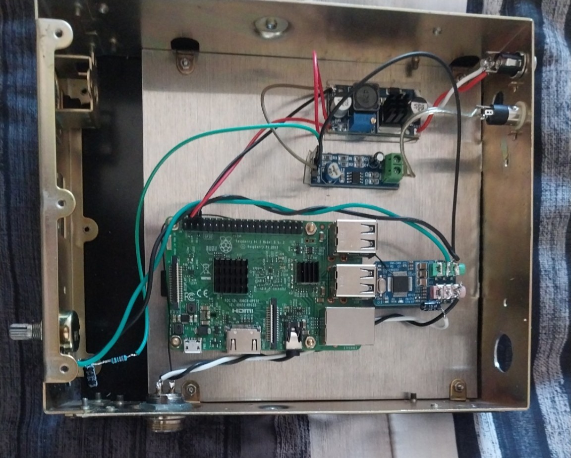
Got it built! But I’m running into lots of problems.
First, I omitted the MAX9814. I’m using the Midland mic which is a speaker mic, so an electret amplifier wouldn’t work anyway. Sounds good, good volume, has a slight hum. Can most likely be adjusted in the menu. Low hum can most likely be fixed with a basic filter.
My biggest challenge right now is receive/audio output. I ditched the PAM8302 and instead went with one of those LM386 modules. Works but has lots of background noise and computer-generated noise which drowns out the node audio. If I remove amplification completely it sounds okay. Can anyone help on fixing this? Would filtering save it or is the 386 just that noisy? I’ve twisted wires into twisted pairs and that still doesn’t seem to help.
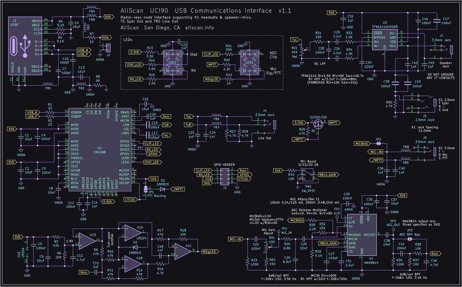
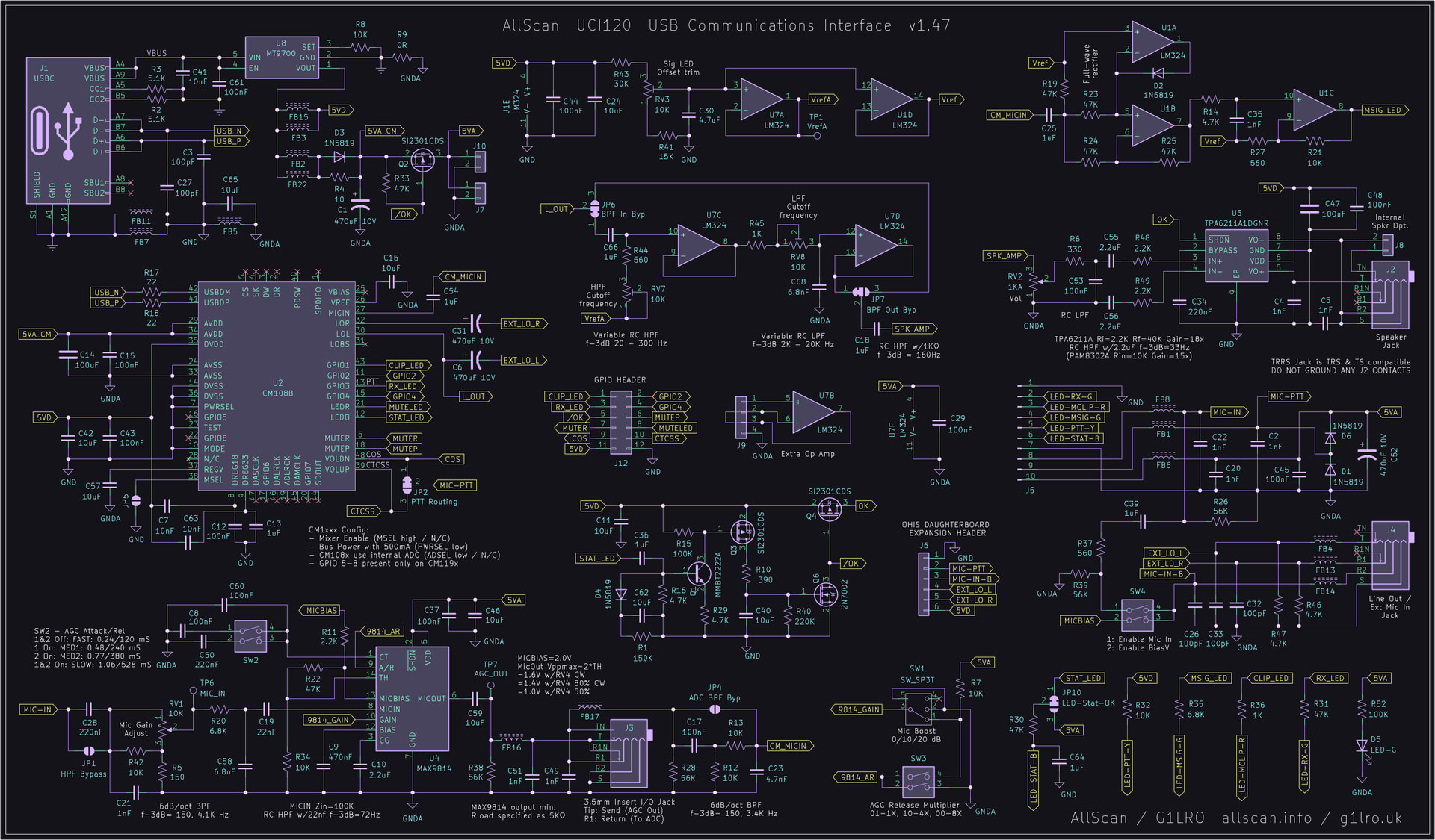
I would suggest taking a look at the schematics for the UCI90 and UCI120. I went with a TPA6211 class-AB audio amp in the UCI90 as well as in later revs. of the UCI120, which can drive single-ended loads yet otherwise has the same specs as the PAM8302. These are both available as assembled & tested PCB’s without enclosure BTW ($79 for a UCI90 PCBA). The UCI90 has over 110 components and the UCI120 about 170, which are each important in achieving excellent audio quality, RFI/noise-resistance, etc.
Both the UCI90 and 120 can work fine with any electret mic ie. can provide standard 2V–2KΩ mic bias for mics that don't have a separate power input.
And yes you can easily add a VU meter to either audio channel. The LM386 are actually fine for driving VU meters, though are otherwise quite useless for actual audio amplification in USB-connected devices as you noticed.
Mark G1LRO has a product that adapts the UCI90 and adds a PiZ2W and OLED display, see G1LRO.uk
Also a quick question on your radioless design…did you happen to notice any harsh buzzes or background noises on the audio output side of things? I tried using the PAM8302 module but couldn’t quite get it to output any audio, which is why I stuck with the LM386 (which I now see isn’t really a good choice audio-wise). I fed it directly from the potentiometer as you had done on your radioless nodes however I have somewhat long wire runs whereas your nodes didn’t. I also used twisted wire pairs but still couldn’t hear a difference. Could the long wire runs be the cause too?
The green/black wires are the audio output wires and the white/black are the mic wires. I have a 10uF cap in series with the mic line and I’ve also gone back and added a resistor from tip to ground on the mic input to reduce the buzzing on transmit. Works decently actually, so problem solved here? I’m sure with further experimentation I could eliminate this noise.
Would using 2-conductor shielded wiring work, like this? I was thinking that I could ground the shield at the CM108 sleeves and leave the accessories (mic jack, audio amp) floating.
Looks like you have a DC-DC converter, those can definitely create a lot of EMI noise. I would get rid of that if possible, or add some ferrites and a ~0.25Ω-1mF RC filter on both sides of it. Slightly longer wires or unshielded wires should not in itself create noise in a radio-less node.
Thank you for the advice, I was starting to wonder if this wasn’t the issue. It’s an LM2596 module off of Amazon.
I’m feeding a 12V 3A supply to it, possibly a stupid question but is there a better way to step 12V down to 5V while keeping the 3A? I wanted to use a 7805 but those can only supply up to 1.5A.
Inexpensive DC-DC converters will usually add a lot of noise on both the input and output at the switching frequency (typ. 100KHz - 1MHz) but this can also result in a lot of noise at lower frequencies. The actual current and variation in current can also affect the noise spectrum. A ~0.25Ω-1mF RC filter on both sides should help a lot, but the R may need to be as low as 0.1Ω or C potentially higher depending on the exact current and noise spectrum characteristics. You can see the noise by looking on a DMM/DSO or plug into an PC audio in (through a ~1uF cap to ensure DC blockage) and look at the noise spectrum in a wav editor with spectrum analysis. Ideally you should have no more than 1mV AC on the input and output lines.
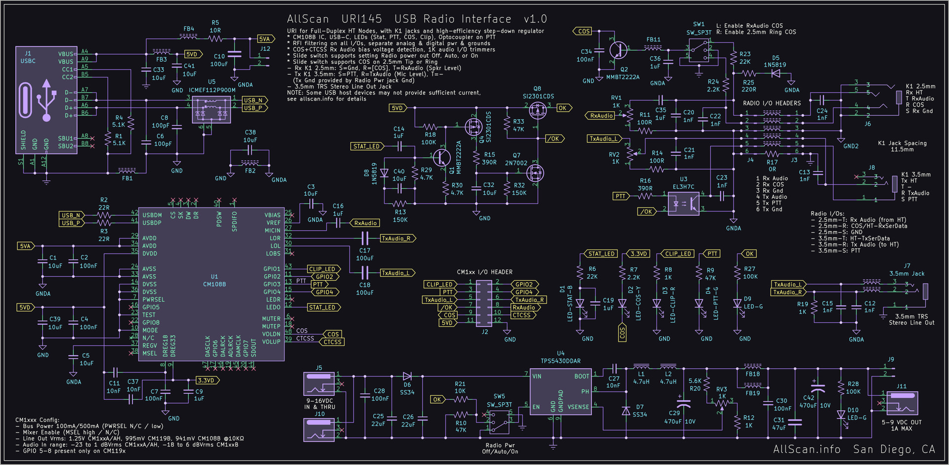
Also take a look at the step-down converter circuit I have in the URI145. This provides very clean DC out that will support 55+dB audio SNR on RT85 HTs. The inductors and ferrites provide some resistance which with the ~1mF capacitance has a f-3dB of ~500Hz which is way below the switching frequency. With properly rated ferrites this will support 3A out.
Looks like the LM386 was gained out to 200x (10uF capacitor between pins 1 and 8). Once I removed the cap it reduced the popping/hissing/fizzing/etc. down to a MUCH cleaner sound (now at 20x gain). I’ve also thrown on some more filter caps and resistors to the input and output and that seems to have tamed the rest. In addition I also utilized star grounding, where I tack soldered each ground from each device to one common square of FR4 board.
Overall a really fun project, and goes to show that there’s more than one way to crack an egg! Next up will be adding a VU meter in place of the S-meter and building a bezel for the OLED.