That does not sound like a ground loop, but power supply ripple from drawing near the max current that can be supplied by the power supply. Switching power supply’s start getting noisy when over 80% capacity.
I would use 1 ea or a bigger one.
The Alinco power supply delivers 30A and I have used it for my 100W HF radios for years. It’s not an overload problem. Currently the only load on that supply is two RT85s, one of them which is only being used as a receiver. The other one is set to low power since I’m using it in in the house. Even then I can be at the outer perimeter of my 5 acres and still get full quieting audio.
I did a lot of testing with a few switching power supplies and although not always necessary I recommend a snap-on ferrite core filter with at least 3-4 turns of the power wires around it – as close to the power supply as possible, and then also add a min. 2200 uF Filter cap – as close to the radios as possible.
I tested 4 different power supplies, one linear and 3 switching, and saw ripple of up to 30mV AC with no extra filter cap but the added cap. dropped it to < 1mV.
The ferrite filter on the other hand prevents conducted RF from getting into the power supply and causing harmonics at 60 Hz mixed with the switching frequency.
BTW I just finished the power supply box for my latest node, I put the Dell adapter and the 7.5V switcher supply inside a 6" x 4" x 2" aluminum box in order to have better shielding and have a nice solid enclosure to anchor all the components. The metal probably makes no significant difference for RFI actually but it does keep the wiring nicely concealed and out of the way.
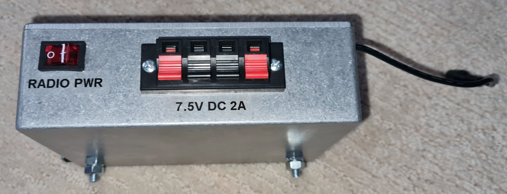
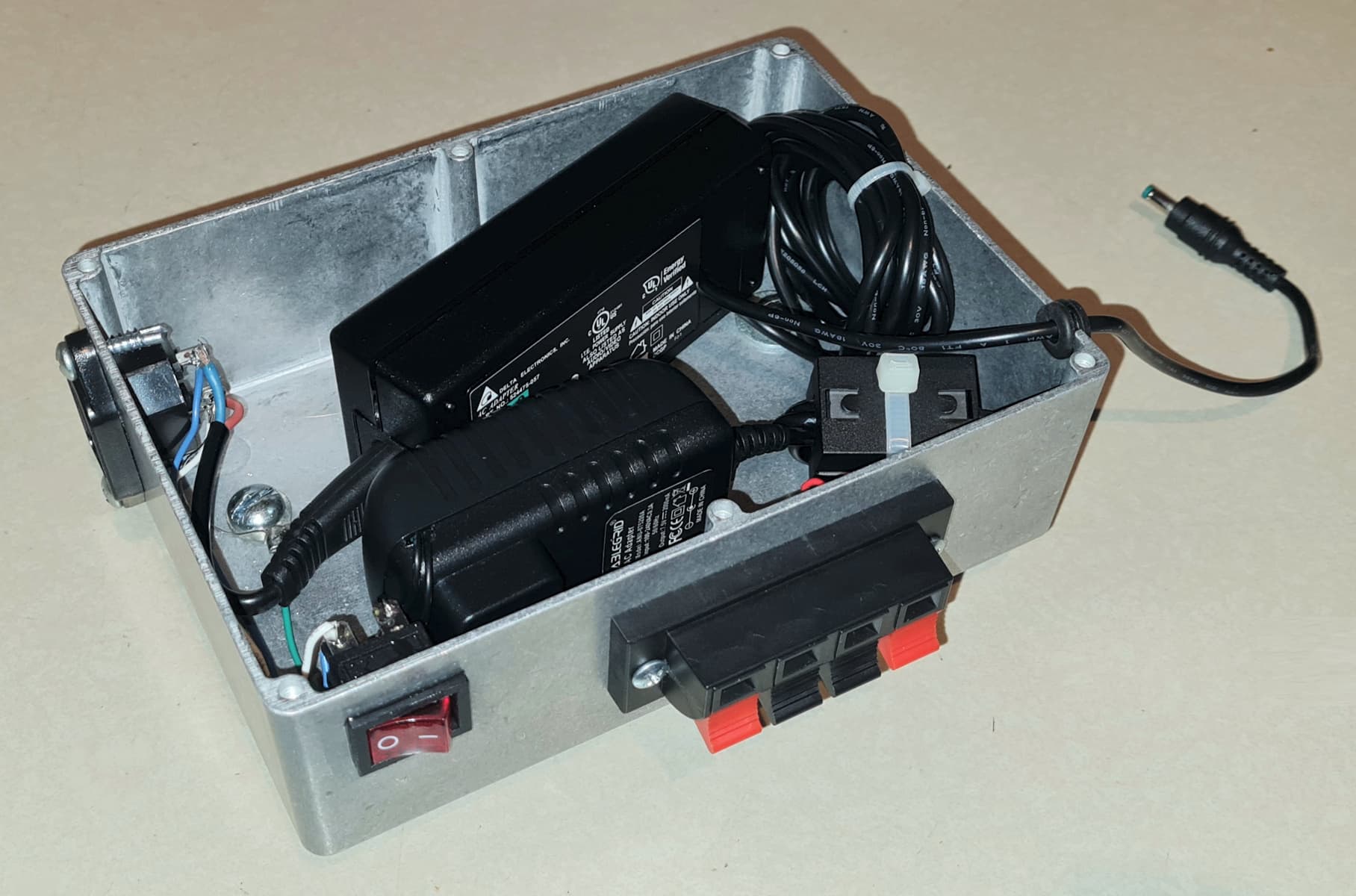
I have tested only FCC-certified switching power supplies (you can get 7.5V 2A switching wall adapters for $10 on ebay/amazon/mouser, this is one I have in the box). No idea how good of supplies Alinco makes, but an RT85 Tx’ing low power uses only 475mA, so a 2 Amp supply gives loads of headroom and there was no noise on the audio in my tests even with no metal box.
So the ferrite filter and extra filter cap are the first step. Second step would be try a different power supply. Ground loops are not typically an issue for RF. Most shacks have numerous ground loops because there is just no way not to when everything is powered from 12V (ground #1) then you have ground wires and coax (ground path #2), and various interconnections/USB/audio cables. At worst that will cause a 60Hz hum somewhere eg. if I go into a mic pre on a mixer I have to use an isolation transformer. But a node as we have set up with a microPC and 2 HTs is standalone with no connections to anything else. Only thing you have is a ground and audio wires going less than a foot to the DRA/RIM audio interface, and the power wires. If you keep all this as short as possible and run all wires parallel to each other there literally won’t be any loops ie. having any actual enclosed area within a plane.
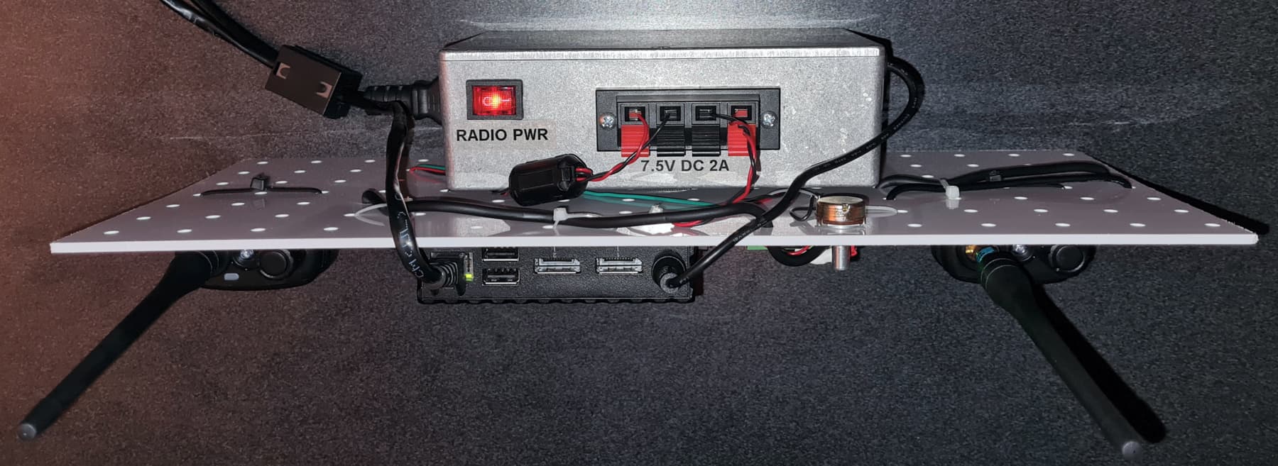
Just finished testing the new node I built and it’s working very well. For this one I used a Repeater-Builder RIM-LiteV2 radio interface and the audio is crystal clear. The level trim pot required no adjustment since the Rx HT has a volume control already, and for the Tx audio I have a 10K audio-taper panel-mount potentiometer at the top of the peg board.
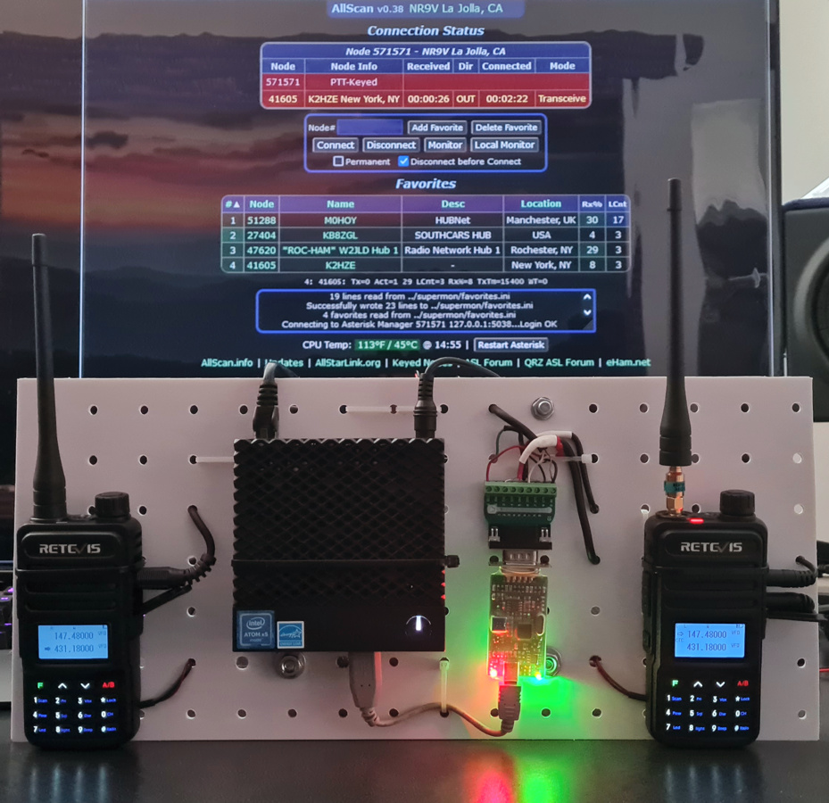
I noticed however that the Tx audio would pick up some noise, apparently due to the Tx HT antenna only being a few inches away from the RIM. I then put a 6dB 2-Watt SMA attenuator inline (see pic above) and that fixed it.
After further investigation I found that with a ferrite filter on the power wires going to the Rx HT that also stops any noise. So either an attenuator or ferrite filter will fix it, and with both you should be very well covered against any possible chance of RFI/noise.
I also have a spare small aluminum box that I tried putting over the RIM-Lite but it didn’t really make much difference. So that’s good news in that the RIM works fine with no case which saves a few $.
(Updated) So in summary if you have any Tx noise these are some simple solutions:
- Put some attenuation in-line with the Tx antenna. The RT85’s put out 1.5 Watts on Low power which is a lot more than you need within ~1 mile of your QTH. 6dB of attenuation reduces that to ~375mW which is much more reasonable.
- Add a small ferrite clip-on filter on the power supply wires to the Rx HT. I already had a ferrite filter inside the power supply box but it was for the power to both HTs. Apparently some RF could still get coupled into the power line to Rx HT however so either you’d want one ferrite right next to the power supply and one on the line to the Rx HT, or separate filters on each line going to each HT.
- Use some other antenna for the Tx HT, such as a small mag-mount antenna 10 feet or so away on a file cabinet or an outdoor antenna or attic antenna. The 1+Watt of Tx RF will then no longer be right next to the node components.
- Check your power supply ripple, try different power supplies, ferrite filters and filter caps as noted previously.