In addendum to the piece I wrote on the topic for network controlled devices…
I found a new animal to play with this year and finally had time to play with it
This one is ttl232 or rs485 & modbus driven. Has a AT command set for simplified control for ttl232 and rs485
But note that I will not go into any detail on modbus info. To much to cover and those that are familiar can quickly adapt on their own. This is for the beginners. See data sheet links below.
So the device is labeled R413E16 / eletechsup and is available in 2 versions. The 'A" version can be quickly mountable to the 16 relay board seen in previous write-up with a header pin arranged at the bottom. ‘B’ version is basically upside down version of the same and will not mount on relay board accurately. Likely find these on ebay, amazon and some other hacker-maker sites.
One important note that the ttl232 inputs are different than the rs485, but if you are to use ttl232 inputs, you need to remove the rs485 chip as it interferes with the data. It is the 8 pin chip. Sorry, it looks like no provision was made for this in the form of a jumper as I doubt it was designed for more than rs485.
Internally, I think they used the ttl232 to program them.
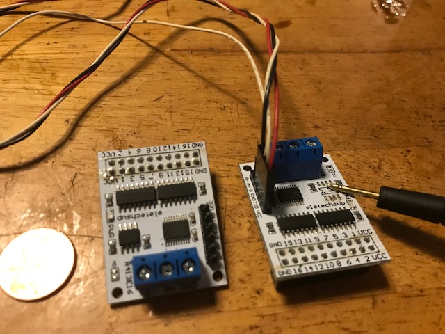
That is a penny for size compare.
Did I mention this is plug and play in the 16 device relay board.(20 pin idc header)
So, if you have ever worked with a ‘AT’ command set, you will find this simple as they come.
I wrote a shell script for this to be able to just call it from the dialplan with even more limited parameters.
Here is the contents of serial-control.sh but you will need to change the tty device to match your usage.
Comments do not format well here.
You might notice the logical 'G" used for 16. Yea, that’s right. Novice asian dev’s I would say. They are not using logical hex number set.
for R413E16 serial 16 output control module with rs485 chip removed -M.Mays 12-25-2022
AT command set valid with both rs232 and rs485 but not in modbus (hex w/2byte CRC)
AT commands
1 - 16 = 123456789ABCDEFG respectively
T(# 1-G) toggle current pos op/cl
O(# 1 - G 123456789ABCDEFG open)
C(# close 1-G)
D(# open 1-G) with delay of seconds represented in 4 digits (D1=0005)
AO = all open
AC = all closed
R(# Read status 1-G) echo’s the status of switch
AC = all close
AO = all open
Lx = turn all off except lock (x)
Mx = turn (x) on momentary 1sec
===============
#! /bin/bash
com=$(echo “$1” | awk ‘{print toupper($0)}’) # convert command to uppercase
echo “AT+$com” > /dev/ttyUSB0 9600 # add AT cmd prefix and command line input, send to device
reply=“$(timeout .05 cat /dev/ttyUSB0)” # get reply from device and print to screen
echo $reply # not valid under rs485
while read -t 0 var < /dev/ttyUSB0 9600; do continue; done #clear buffer
=================
shell available for download, includes commented out command list
- check/set owner / permissions before use
https://kttycat.com/dl-files/serial-control.sh
You could also convert the dialplan I posted for the other with methods mentioned within the network control of previous post or perhaps later I will add one here.
./path/serial-control.sh t2 - will toggle relay 2 from off to on or on to off depending on its current setting.
data on device from dev that I keep stored
https://kttycat.com/dl-files/serial-modbustool.zip
Know that there are a lot of countries and IP ranges blocked from my servers. Sorry !
Late additional I perhaps should have included…
The bash script basically converts the command line to upper case as that is what is required for device input.
And inserts the AT+ and then your command you issued (shellcript.sh T3 (toggle #3))
Then clears any reply in the serial buffer.
You don’t have to use the script if you run your command in uppercase and include the output device in the command line with speed. The shell script makes it simpler, and as I do, write other stuff into it.
Like complex combinations for sequencing and a special command for that sequence selection.
As I normally use this example,
I have a backup diesel generator. When my solar controller batteries are low, I need to sound a alarm near it for 10 seconds, then turn the ignition on, then fire the glow plugs for 10 seconds, then initiate the starter for 4 seconds while the glow plugs are still on, then turn it all off when the controller throws it’s switch to say it’s charged to a level I have set.
So you can see that complex actions can be made with a simple device that has 16 switches, and a computer for a timer / actuator.
The physical connection from the device to a ttl232 device is straight forward.
5v, ground and a swap from tx to rx and rx to tx between them. (one device tx is the others rx)