I have decided to build an allstar node. Got the radio, got the account,
got the URI, got the Linux box, got the software, now I have to build the
cable and put it all together.
But in looking at the cable description on the DMKeng site, I don't see
any COS signal used.
Isn't the COS from the radio needed to suppress transmitting dead autio
over the network? I thought a COS signal was required. It's talked about
as necessary but the signal isn't shown in the gm300 cable description.
Anyone care to explain why this is not needed or when it is needed? And
if it is needed, which pin on the 25 connector would it go to?
<-- Hi Mike; Welcome to Allstar! - the diagram that you reference above shows the use of "flat audio" from the GM300. I often get questions about the RX audio and my response is usually, "raw discriminator audio, with a flat frequency response from a few Hz up to around 5kHz"
The Allstar (app_rpt) software can be setup to use DSP - i.e., it can decode the raw audio to detect PL.... this method is much faster than using a COS line, which can sometimes be very sluggish.
So for this reason, COS is not mandatory - assuming that the radio of choice can provide the raw discim audio with a flat frequency response; and the GM300 can.
Hope this helps.... I am on a train and approaching my stop.
Cheers!
Ramesh.
Admin for many things!
···
On 10/04/2013 5:05 PM, Mike wrote:
I have decided to build an allstar node. Got the radio, got the account,
got the URI, got the Linux box, got the software, now I have to build the
cable and put it all together.
But in looking at the cable description on the DMKeng site, I don't see
any COS signal used.
Isn't the COS from the radio needed to suppress transmitting dead autio
over the network? I thought a COS signal was required. It's talked about
as necessary but the signal isn't shown in the gm300 cable description.
Anyone care to explain why this is not needed or when it is needed? And
if it is needed, which pin on the 25 connector would it go to?
Its simply cause the app_rpt app will detect the cos by dsp and the same will be done for any ctcss tone you want.
That if you use USBRADIO
If you use SIMPLEUSB you will need to to provide COS and ctcss if you want ctcss.
-----Message d'origine-----
···
From: Mike
Sent: Wednesday, April 10, 2013 5:05 PM
To: app_rpt-users@ohnosec.org
Subject: [App_rpt-users] GM300 Cable pinout question
I have decided to build an allstar node. Got the radio, got the account,
got the URI, got the Linux box, got the software, now I have to build the
cable and put it all together.
But in looking at the cable description on the DMKeng site, I don't see
any COS signal used.
Isn't the COS from the radio needed to suppress transmitting dead autio
over the network? I thought a COS signal was required. It's talked about
as necessary but the signal isn't shown in the gm300 cable description.
Anyone care to explain why this is not needed or when it is needed? And
if it is needed, which pin on the 25 connector would it go to?
you did a way better job them me at explaining this ;-)))
-----Message d'origine-----
···
From: Ramesh Dhami (VA3UV)
Sent: Wednesday, April 10, 2013 5:16 PM
To: app_rpt-users@ohnosec.org
Subject: Re: [App_rpt-users] GM300 Cable pinout question
On 10/04/2013 5:05 PM, Mike wrote:
I have decided to build an allstar node. Got the radio, got the account,
got the URI, got the Linux box, got the software, now I have to build the
cable and put it all together.
But in looking at the cable description on the DMKeng site, I don't see
any COS signal used.
Isn't the COS from the radio needed to suppress transmitting dead autio
over the network? I thought a COS signal was required. It's talked about
as necessary but the signal isn't shown in the gm300 cable description.
Anyone care to explain why this is not needed or when it is needed? And
if it is needed, which pin on the 25 connector would it go to?
<-- Hi Mike; Welcome to Allstar! - the diagram that you reference above
shows the use of "flat audio" from the GM300. I often get questions
about the RX audio and my response is usually, "raw discriminator audio,
with a flat frequency response from a few Hz up to around 5kHz"
The Allstar (app_rpt) software can be setup to use DSP - i.e., it can
decode the raw audio to detect PL.... this method is much faster than
using a COS line, which can sometimes be very sluggish.
So for this reason, COS is not mandatory - assuming that the radio of
choice can provide the raw discim audio with a flat frequency response;
and the GM300 can.
Hope this helps.... I am on a train and approaching my stop.
1) The DSP chip inside the URI can decode the COS and know when it's
present. Therefore, having a separate COS isn't required.
2) Since the diagram shows wiring for this case, can I assume that pin 11,
on the GM300 connector, is the correct RX to use, use for receive audio,
to the URI?
3) Is there anything else required (changes inside the radio) for this wor
work correctly?
4) Since the tone is decoded in the DSP, where do I specify what that tone
is, so the app_rpt software knows what tone to look for?
Mike
···
On 10/04/2013 5:05 PM, Mike wrote:
I have decided to build an allstar node. Got the radio, got the
account,
got the URI, got the Linux box, got the software, now I have to build
the
cable and put it all together.
But in looking at the cable description on the DMKeng site, I don't see
any COS signal used.
Isn't the COS from the radio needed to suppress transmitting dead autio
over the network? I thought a COS signal was required. It's talked
about
as necessary but the signal isn't shown in the gm300 cable description.
Anyone care to explain why this is not needed or when it is needed? And
if it is needed, which pin on the 25 connector would it go to?
<-- Hi Mike; Welcome to Allstar! - the diagram that you reference above
shows the use of "flat audio" from the GM300. I often get questions
about the RX audio and my response is usually, "raw discriminator audio,
with a flat frequency response from a few Hz up to around 5kHz"
The Allstar (app_rpt) software can be setup to use DSP - i.e., it can
decode the raw audio to detect PL.... this method is much faster than
using a COS line, which can sometimes be very sluggish.
So for this reason, COS is not mandatory - assuming that the radio of
choice can provide the raw discim audio with a flat frequency response;
and the GM300 can.
Hope this helps.... I am on a train and approaching my stop.
1) The DSP chip inside the URI can decode the COS and know when it's
present. Therefore, having a separate COS isn't required.
No there is no DPS chip on the URI, this is done by the DSP code in the
computer.
2) Since the diagram shows wiring for this case, can I assume that pin 11,
on the GM300 connector, is the correct RX to use, use for receive audio, to
the URI?
Yes, Pin 11 is correct for this if JU551 is in position A
3) Is there anything else required (changes inside the radio) for this wor
work correctly?
See Above.
4) Since the tone is decoded in the DSP, where do I specify what that tone
is, so the app_rpt software knows what tone to look for?
the COS/COR is not needed because the settings in the usbradio.conf are
going to be:
carrierfrom=dsp
ctcssfrom=dsp
The Linux box is going to use DSP to detect the the difference between
the white noise and a modulated signal. Once it detects that difference,
it will send the audio over the network to whatever node you are
connected to.
Ensure that you use the radio-tune-menu after you make the setting
adjustments and reboot. The radio-tune-menu going through the steps will
help you ensure that your audio into the network is set to the proper
deviation, ability to detect the difference between white noise and an
actual signal, and proper TX audio levels on your end. This will ensure
your TX deviation is set to 3KHz with a 1KHz tone and vise-versa.
It is wise to use a service monitor when using the radio-tune-menu. If
you do not have access to one, become a friend with someone who does, or
ask members of your radio club. I'm after two or three hours of pure,
continuous looking, you will find someone who has one.
The allstarlink.org website has an alternative method that uses a radio
that should be known accurate. Meaning it's TX audio deviation is
correct, and it's on frequency, as best as a amateur radio is going to
be. If you do not have a tone generator, the open source world has
plenty of programs that you can use the computer to generate a 1KHz
tone.
It's not complicated, and doesn't take long to setup using a service
monitor. Once you go through the steps, the last step will be to save
what you've done and then reboot the node.
I used the above methods to setup my box, and it's works wonderful.
~Benjamin, KB9LFZ
allstar 28569
···
On Wed, 2013-04-10 at 14:05 -0700, Mike wrote:
I have decided to build an allstar node. Got the radio, got the account,
got the URI, got the Linux box, got the software, now I have to build the
cable and put it all together.
But in looking at the cable description on the DMKeng site, I don't see
any COS signal used.
Isn't the COS from the radio needed to suppress transmitting dead autio
over the network? I thought a COS signal was required. It's talked about
as necessary but the signal isn't shown in the gm300 cable description.
Anyone care to explain why this is not needed or when it is needed? And
if it is needed, which pin on the 25 connector would it go to?
Mike
_______________________________________________
App_rpt-users mailing list
App_rpt-users@ohnosec.org ohnosec.org
Although I retired out of the two-way radio field I’m not totally familiar with every radio that’s been produce for the last 20 to 30 years, especially when it comes to programming the accessories pins on some of the Moto radios like the GM-300. And, since I’ve been tasked with the request to set up a Repeater with Allstar for our radio club it is for that reason I must inquire about the settings in the code plug and how they are to be programmed… One of the questions above asked:
“3) Is there anything else required (changes inside the radio) for this work correctly?
See Above.”
Sorry, I’m not seeing where this was addressed “above”. So I must ask,
So what would be the proper settings in the Code plug for the ““Radio Wide Configuration”? Would I use the selection of “Radius Rick-RX” or one of the others, and then once that selection is done, selecting “F9” for additional Accessories” would I leave the pins as “Default” or change which pins to what?
Many of the other Motorola radios made after the GM-300 are pretty easy to figure out, it’s just this one radio I’m using as a receiver that I’m having issues with since it does not have the “COS” pin option.
Hi William, I’ve been using GM300 radios for some years and I love them.
About the accesory connector, I usually use the “General I/O” setting and then I customize the pins by pressing “F9”. Then, for about the 99% of the situations I only change function of pin 8 to “PL/DPL & CSQ Det” which provides an indication either of carrier present or PL/DPL decode which that depends on how you configured the mode (channel) “RX Squelch Type”. The active level depends on your interface circuit.
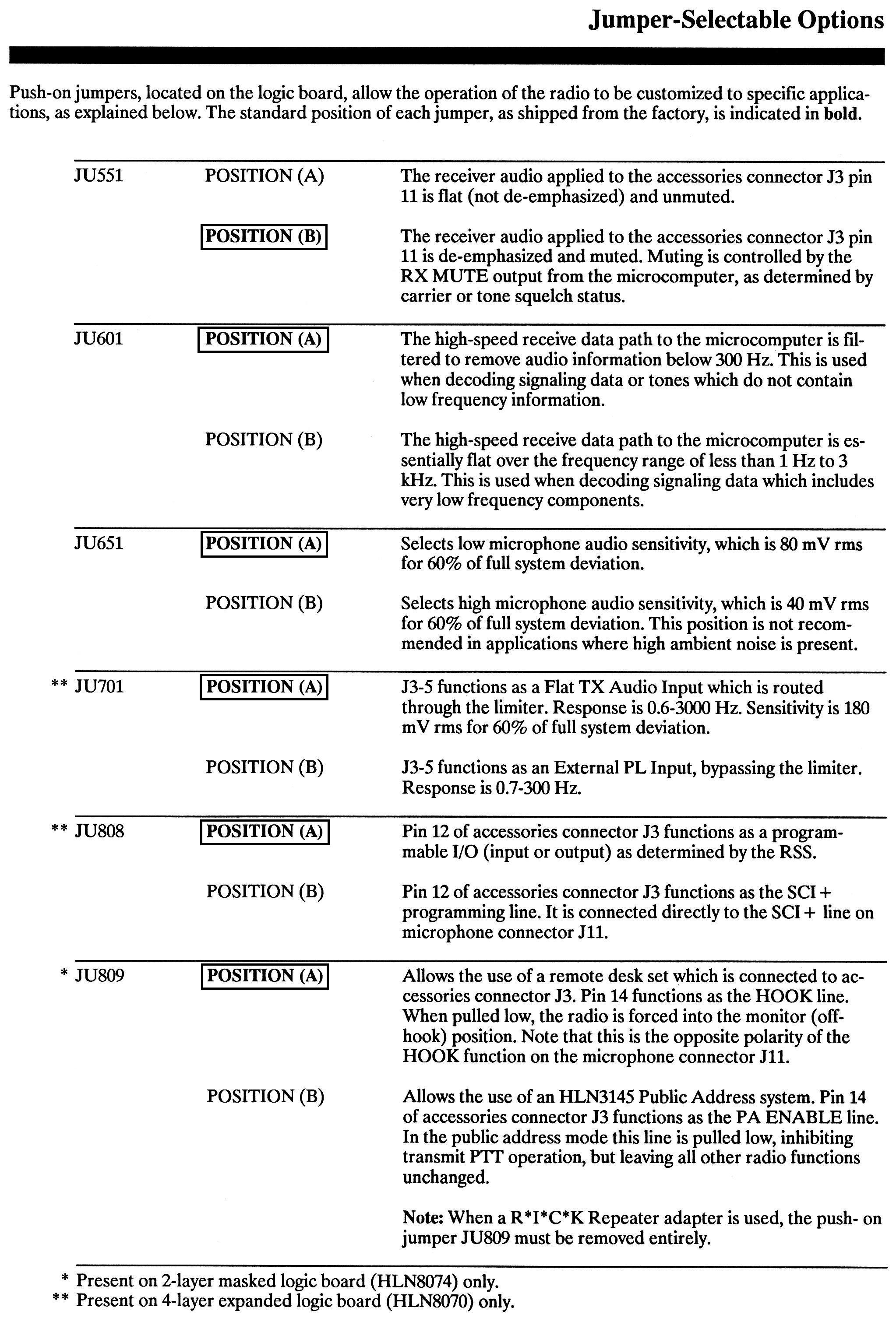
Lastly, the RX audio is taken from pin 11 and there are two options, flat (deemphasized and unmuted) or filtered (deemphsized and muted, the last means that is controlled by the squelch circuitry). These two options are selected by means of JU551 (bottom board of the radio). Please check the following link: http://www.repeater-builder.com/motorola/maxtrac/gm300-info/gm-jumpers.jpg
Hope this will help.
Regards.
Gustavo - LU7WA
(By the way this is my first post so thanks for letting me in!)
Hi William, I’ve been using GM300 radios for some years and I love them.
About the accesory connector, I usually use the “General I/O” setting and then I customize the pins by pressing “F9”. Then, for about the 99% of the situations I only change function of pin 8 to “PL/DPL & CSQ Det” which provides an indication either of carrier present or PL/DPL decode which that depends on how you configured the mode (channel) “RX Squelch Type”. The active level depends on your interface circuit.
Lastly, the RX audio is taken from pin 11 and there are two options, flat (deemphasized and unmuted) or filtered (deemphsized and muted, the last means that is controlled by the squelch circuitry). These two options are selected by means of JU551 (bottom board of the radio). Please check the following link: http://www.repeater-builder.com/motorola/maxtrac/gm300-info/gm-jumpers.jpg
Hope this will help.
Regards.
Gustavo - LU7WA
(By the way this is my first post so thanks for letting me in!)
Although I retired out of the two-way radio field I’m not totally familiar with every radio that’s been produce for the last 20 to 30 years, especially when it comes to programming the accessories pins on some of the Moto radios like the GM-300. And, since I’ve been tasked with the request to set up…
Hi William,the pin setting is ok but the active level depends on your interface. If you are not sure you can try both or just leave one setting and change the config in the file usbradio.conf
carrierfrom = dsp    ; no,usb,usbinvert,dsp,vox
                                ; no - no carrier detection at all
                                **; usb - from the COR line on the USB sound fob (Active high)**
**                                ; usbinvert - from the inverted COR line on the USB sound fob (Active low)**
                                ; dsp - from RX noise using DSP techniques
                                ; vox - voice activated from RX audio
The DMK diagram is correct. You do NOT need to connect a COS signal in order to get the URI and allstar to recognize a valid signal; it’s all done in software now.
I’ve never used COS on any batwing radio I have; the 16- and 20-pin accessory connectors on the back are all wired the same it seems. Pin 3 is PTT, Pin 5 is TX Audio, Pin 7 is GND, and Pin 11 is RX audio. 4 connections.
As someone else mentioned, you have to make sure that the JU551 on the bottom board is set right, it’s just a typical DIP jumper to ensure your signal out of pin 11 is flat discriminator audio so the software can deal with deriving the presence of signal versus the white noise of a non-occupied channel. http://www.repeater-builder.com is your friend (as it has been mine for over 12 years of running a network of repeaters…).
Not saying that you can’t spin up your RSS and configure a pin (IIRC, it’s pin 8) as a COS signal and configure allstar to recognize it, but, I’ve found that it’s easiest to use the least number of connections between devices and use the software to figure out what’s going on rather than complicating things with multiple connections; the fewer you have, the more generic (ie if you decide you want to put a CDM1250 in place of a GM300, you just swap bricks and go to town…) is the set up and less debugging of signal directions, high or low, or what have you.