Marshall is correct, and Marshall has helped me with this project as well.... Thank you Marshall.
I suspect there has to be an underlying configuration file still. It's still Debian under the hood. If I can get to it, and modify it... that is still to be seen.
What wattage does the 47k ohm resistor need to be? 1/8, 1/4, 1/2, 1, 2? Does it matter? Ditto on the NPN transistor. It sucks radio shack doesn't exist anymore, it's now a pain to find the components locally.
Thanks
--Bret Taylor
Olympia School District
On Sun, Mar 10, 2019 at 10:54 PM Marshall Oldham <ke6pcv@cal-net.org > <mailto:ke6pcv@cal-net.org>> wrote:
FYI,
He is not using app_rpt software with the URI, he is using the
Bridgecom MV-iL hardware with a URI to interface to his GE Mastr III
So he can not set CORFROM=uisbinvert in software config.
73
Marshall
*From:*App_rpt-users
[mailto:app_rpt-users-bounces@lists.allstarlink.org
<mailto:app_rpt-users-bounces@lists.allstarlink.org>] *On Behalf
Of *REDBUTTON_CTRL
*Sent:* Saturday, March 09, 2019 5:24 PM
*To:* app_rpt-users@lists.allstarlink.org
<mailto:app_rpt-users@lists.allstarlink.org>
*Subject:* Re: [App_rpt-users] GE Mastr III and DMK USB-URI
Bret, one thing to know about the URI is that the COR input line
(pin 8) requires a signal transition to pull to ground. This is
different that a signal that sources voltage and goes low. the URI
has internal pullup resistors so it doesn't look for voltage change.
So what this means is if the CAS/COR out line on the Master III
does not pull to ground when it goes low, the URI will not see a
signal change. The URI has a dc blocking diode on its input. So it
needs to see a signal that either goes low when the receiver is
active or when it is inactive.
If the Master III CAS/COR is active hi then I suggest you connect
the CAS/COR through a 47K resistor then to the base of an NPN
transistor. Then connect the collector to pin 8 on the URI and
connect the emitter to gorund. This will invert the CAS/COR signal
and give an open collector that goes to ground on receiver activity.
Then in the Allstar node set the CORFROM=usbinvert.

This means the URI will be looking for a signal to ground pin 8.
then audio will be sent through the system.
Hope this helps.

Regards,

Jon VA3RQ
On 3/9/2019 8:26 AM, Bret Taylor wrote:
"What channel driver are you running? This will determine what
sort of audio
you need from the system and where squelch is performed."
I'm using a Bridgecom MV-i1 to drive the URI -
https://www.bridgecomsystems.com/collections/tl-net/products/mv-1
I don't know exactly what is under the hood. Their "OS" is called
TL-Net. But under that is Raspbian. I have a network of TRBO
repeaters that the MV-i1 taps into through IP Site Connect.
I'm trying to bridge the TRBO repeaters to this Mastr III base
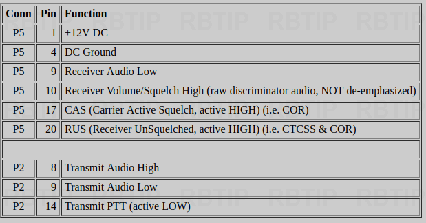
station. I've already created a cable using the info from
MASTR III Stations External Repeater Controller Interface
I created a bridge group in TL-Net to bridge the analog interface
to IPSC masters. I can PTT on a DMR programmed to the correct Call
Group, and hear it on a Analog radio tuned to the Mastr III
frequency. But I can not hear the Analog radios return, it
doesn't seem to trigger the URI.
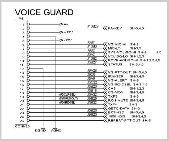
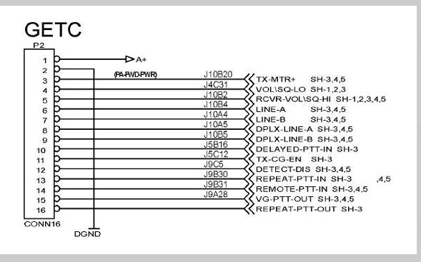
If I use pin 8 on the URI (active low) and connect it to P5-17, or
P5-20 (COR & CTCSS both Active High) on the Mastr III backplane,
the URI goes into a broadcast storm. Using any of the optional
pins for COR (2 & 3 both listed as active high) nothing happens. I
suspect since these are GPIO, the configuration (for the URI?) is
incorrect.
I know the URI works, as I was able to use it to drive an XPR5550e
programmed to the analog frequency of the Mastr III. It's just not
the best situation to run it like that. You clearly hear dispatch,
but since I'm not tapped onto the return path of the antenna
connected to the Mastr III, the mobiles response clarity is
dependent on the proximity to the antenna of the XPR5550e.
"Double check your programing too, as the Mastr III IO is based on
programing.
You'll need to ensure you have your de-empahsis and pre-emphasis
setup
              properly too."

                I do not have the Mastr III programming software
(and can't seem
to find it anywhere). Another user in this list says he has it,
but it searching for it. So, I have no idea how it's programmed.
It's possible the backplane connecters for audio out are disabled?
Thanks for your help.
--Bret Taylor
Olympia School District
_______________________________________________
App_rpt-users mailing list
App_rpt-users@lists.allstarlink.org
<mailto:App_rpt-users@lists.allstarlink.org>
http://lists.allstarlink.org/cgi-bin/mailman/listinfo/app_rpt-users
To unsubscribe from this list please visit
http://lists.allstarlink.org/cgi-bin/mailman/listinfo/app_rpt-users
and scroll down to the bottom of the page. Enter your email
address and press the "Unsubscribe or edit options button"
You do not need a password to unsubscribe, you can do it via email
confirmation. If you have trouble unsubscribing, please send a
message to the list detailing the problem.
_______________________________________________
App_rpt-users mailing list
App_rpt-users@lists.allstarlink.org
http://lists.allstarlink.org/cgi-bin/mailman/listinfo/app_rpt-users
To unsubscribe from this list please visit http://lists.allstarlink.org/cgi-bin/mailman/listinfo/app_rpt-users and scroll down to the bottom of the page. Enter your email address and press the "Unsubscribe or edit options button"
You do not need a password to unsubscribe, you can do it via email confirmation. If you have trouble unsubscribing, please send a message to the list detailing the problem.