I have prepared a CM108 fob as per Allstarsetup Website and wish to connect it to an Icom IC-38 transceiver.
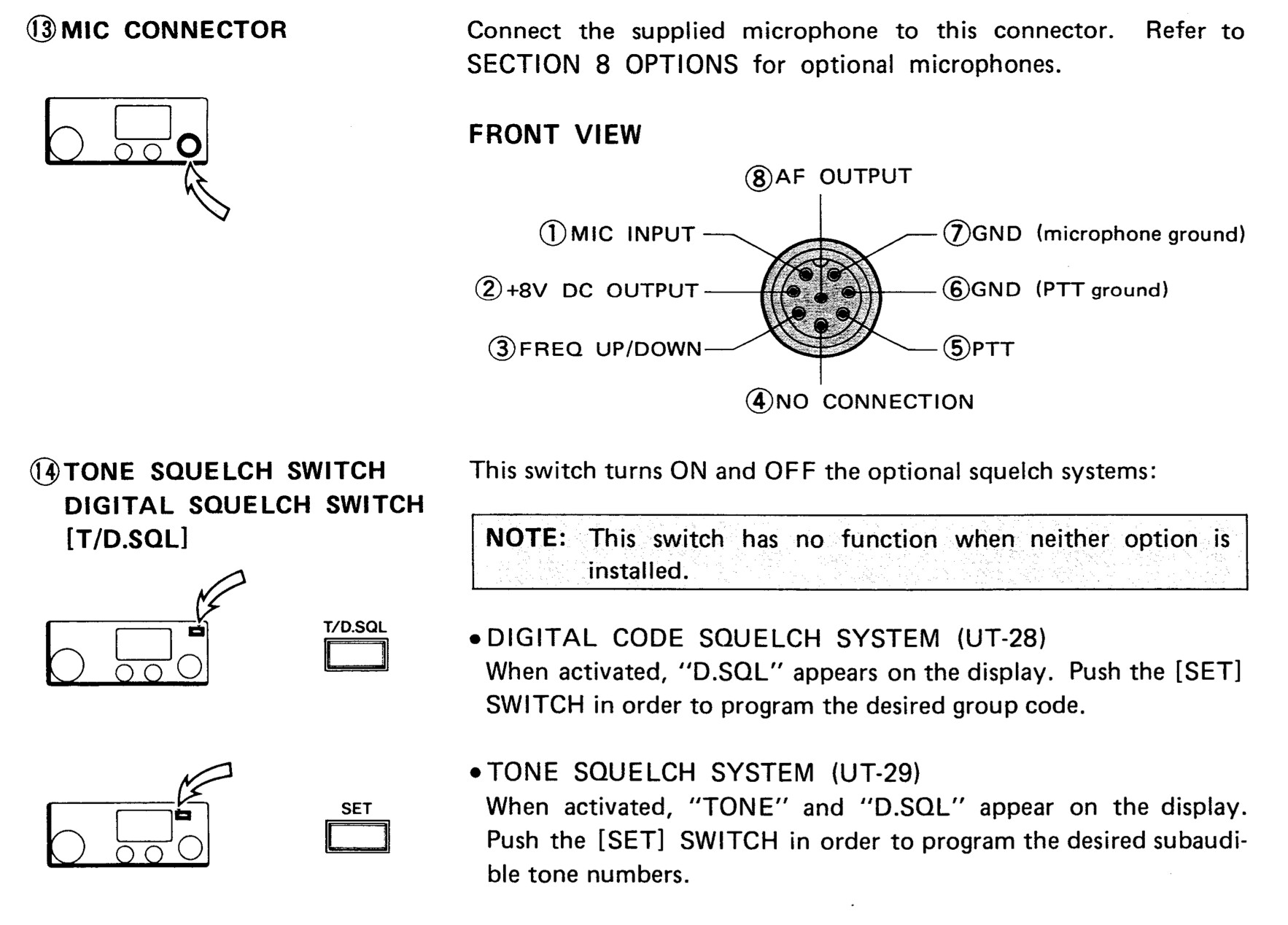
It is a fairly old radio and has an 8-pin connector for the microphone as well as a port on the back for external speaker. A screenshot from the mic pin section of its manual is given below.
I have attached the CM108 speaker (TX) wire to pin 1 of the radio, PTT to pin 5, ground to pin 6 however I am not sure where to connect the COS and RX wires (Radio audio output which connects to CM108 mic audio in).
Will I have to open up the radio for that or could I use the external speaker wire to get COS and audio?
Any help would be greatly appreciated. Service manual can be downloaded from here and regular manual is available on Icom website.
It seems to me I set one of these radios up as a emergency backup for the local club 30 years ago.
The radio was mine I used as a backup on packet BBS.
I had to go inside the radio and find the squelch gate for the cos. Schematic required.
Or, you might be able to obtain it from the "busy light" when the squelch is open. If it still works.
The audio I think was from the speaker that I padded down to about a line level. since I had the attenuated plug in a 1/8" jack already, but you should probably check that af out pin on the mic plug first. It's likely what you want.
You might run a line from that busy led to the unused pin on the mic to make a clean PNP setup.
Thanks for the guidance. I have the schematics but cannot upload them here. I attached COS to the LED and TX to AF Output. In the picture above, mic has its own ground. Does that need a separate connection to the CM108 fob?
Link for schematics is available above.
Another issue is that COS doesn't show as keyed in simple-tune menu when I transmit from handheld. I used carrier = usb (usbinvert shows keyed even when idle and all my other nodes with same fob configuration are also on usb)
I opened up the radio and added a line to pin 4 going straight to the RX/TX LED (which is still working). I checked that when in RX, it glowed green and voltage went up to 2V on the left leg. That is where i soldered the wire from pin 4. Once connected to fob, the light won't turn on during RX. when the fob wire is removed from 8pin connector light starts acting as normal again.
RX audio statistics show the following when I press PTT on handheld;
RxAudioStats: Pk -33.0  Avg Pwr -35  Min -36  Max -35  dBFS  ClipCnt 0
RxAudioStats: Pk   0.0  Avg Pwr -17  Min -36  Max  -4  dBFS  ClipCnt 52
RxAudioStats: Pk   0.0  Avg Pwr  -7  Min -29  Max  -1  dBFS  ClipCnt 774
RxAudioStats: Pk   0.0  Avg Pwr  -6  Min -27  Max  -2  dBFS  ClipCnt 724
RxAudioStats: Pk   0.0  Avg Pwr  -8  Min -24  Max  -1  dBFS  ClipCnt 330
RxAudioStats: Pk   0.0  Avg Pwr -10  Min -26  Max  -5  dBFS  ClipCnt 47
RxAudioStats: Pk   0.0  Avg Pwr  -7  Min -27  Max  -3  dBFS  ClipCnt 438
RxAudioStats: Pk   0.0  Avg Pwr  -7  Min -27  Max  -1  dBFS  ClipCnt 706
RxAudioStats: Pk   0.0  Avg Pwr -20  Min -29  Max  -5  dBFS  ClipCnt 20
RxAudioStats: Pk   0.0  Avg Pwr  -4  Min -27  Max  -1  dBFS  ClipCnt 1781
RxAudioStats: Pk   0.0  Avg Pwr  -4  Min -25  Max  -0  dBFS  ClipCnt 1932
RxAudioStats: Pk  -0.0  Avg Pwr -11  Min -60  Max  -0  dBFS  ClipCnt 354
RxAudioStats: Pk -33.6  Avg Pwr -36  Min -36  Max -35  dBFS  ClipCnt 0
PTT flash is working when sent from interface tune CLI, however time status etc. don't key PTT when I type rpt cmd 1998 status 12 xxx. When I connect it to my main node and TX on that, the IC-38 also transmits and audio quality is not the best but passable, so PTT is working.
Would you have any clue as to what needs to be done to get it working again? Sorry I am a complete noob when it comes to electronics.
You will need to buffer that output with a transistor. 2n2222 etc
You probably should ground it in whatever way the mic is normally grounded.
I don't know if it is the same as frame ground or not so use the provided in the jack.
Or yes, ground to the fob - mic. Same as the spr I believe.
Should the transistor be connected in series between the LED leg and fob, C to B? Sorry, I don't have a clue, but I can follow instructions well.
I forgot to mention earlier but I did add an almost 9k resistor (1k+1k+6.7K in series as I didn't have an extra 10k resistor) in series to the COS line with the same results. I have lots of other resistors but ran out of 10k in case a bigger number will do.
I would dig out the schematic diagram and find unfiltered audio (discriminator) and use about 56K or so to the mic in on the dongle. Then located the CTCSS tone input to the modulator or similar and direct modulate the transmitter - usually 560 ohms or so in the spkr lead. This allows you to use usbradio and let the dsp in allstarlink handle ctcss decode, squelch and direct mod encode. Solder a #30 wire to pin 13 on the CM108 and secure with E6000 glue (so you don't accidentaly pull the wire loose) Install a 2n2222 or other garden variety npn silicon transistor - (I remove the jacks with hot air to make room) I solder the emitter to a ground pad, use 5.6k to the wire on pin 13 (GPIO port for PTT) and use the collector for the PTT keyline. 4 wires from the dongle - GND - PTT, RX and TX audio and you are there. YMMV de nu5d
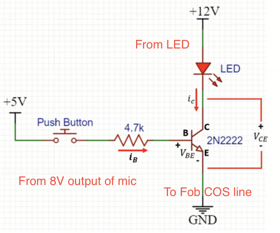
My CM108 fob has a 2n2222a transistor connected as per this screenshot. I already have a line from pin 42 and pin 13. I thought @Mike was referring to another transistor on the LED. At the moment a wire is directly taken from the LED to pin 4 of the mic connector. The light is not turning on as it should after this connection or even when fob is disconnected from PC.
The cos line is pulling the voltage to low on the led.
You need to buffer the line of the LED with a transistor.
You can get handy power for the transistor from that 8v line at the mic connector.
You might also mount the transistor external at the sound fob and get 5v power for the transistor from the sound fob.
There is a line level audio output at the mic connector.
Thank you so much @Mike, I'll do that right away. Just to confirm I am going to do it right, as per the link you shared, I will connect pin 4 mic (connected to LED) to the Collector, and pin 2 mic (8V) to Base of transistor and Emitter to fob. Would that be the right way to do it?
Ok, I watched a couple of videos on transistors and I think collector should be 8V line, base should be line from LED light and emitter should go to COS line on radio.
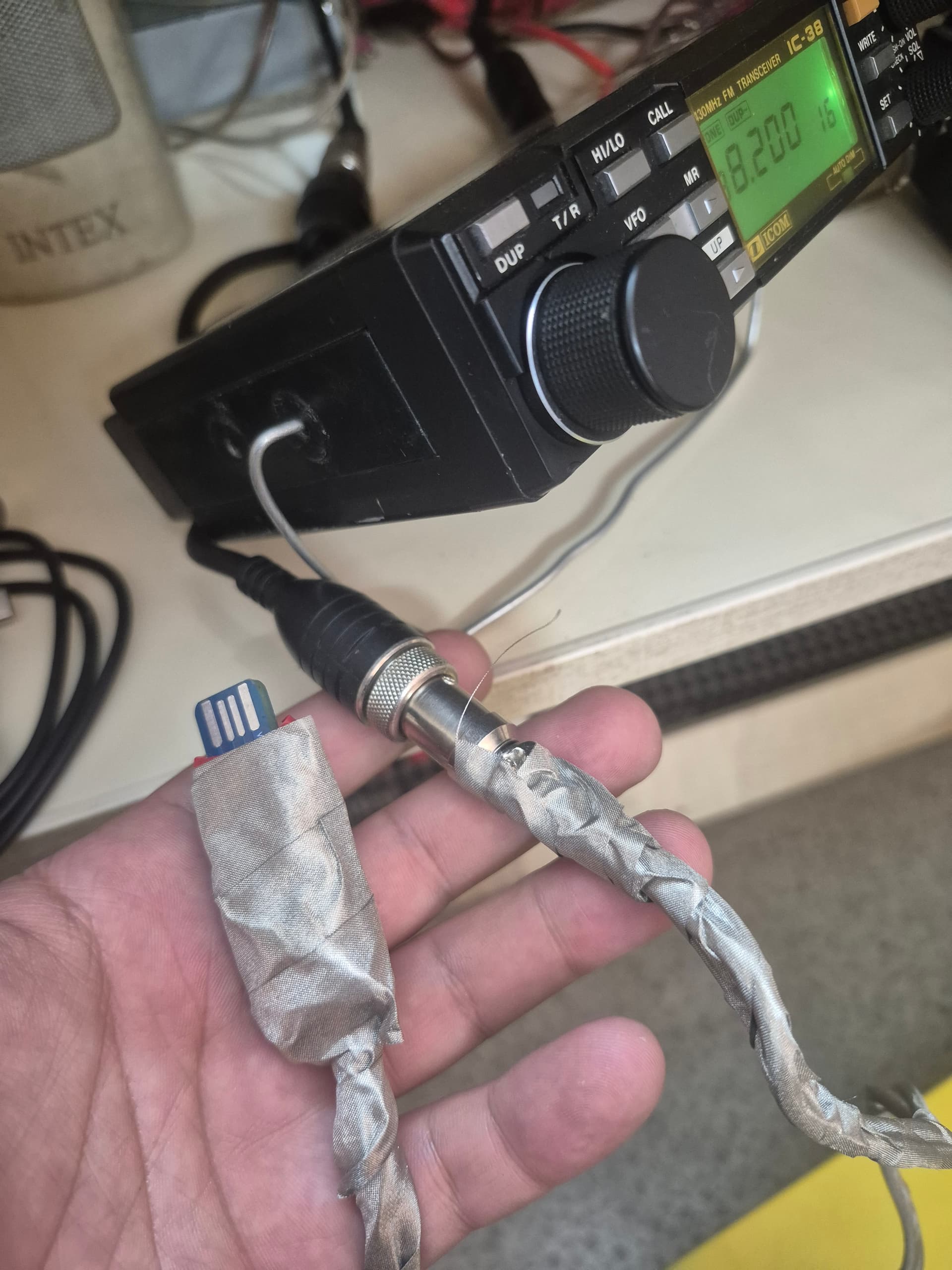
Thank you so much for the help! I have gotten it working. Issue was the cable I was using. I had attached a piece of ethernet wire which for some reason was not passing voltage on COS line.
I changed it to a USB wire and voila. The wires are about 2 feet so there is some electric humming, even though I attached a couple of 100nF capacitors in series on the TX line.
Any suggestions on what could help reduce it further?
RX line from the image is connected to pin 8.
TX line is connected to 2 x 100nf capacitors in series (#103) and then to pin 1 of the mic jack.
PTT is connected to pin 5.
COS is connected to pin 4. Inside the radio, a wire was soldered to the right side leg of the radio LED. This wire was routed through to the connection jack for pin 4 (It was the yellow wire in my radio which is IC-38, not IC-38A).
Ground is connected to pin 6 on the mic jack and to the empty connection point above transistor leg and to the right of PTT on CM108 fob in the picture.
ASL3 is set at half duplex. RX of node radio is extremely dependent on volume knob level therefore a mark on the radio for optimum levels will help get back to how it sounded in case it is fidgeted with.
Carrierfrom = usbinvert
CTCSSfrom = no
EDIT: Hum removed by wrapping fob and wire with metallic conductive tape.