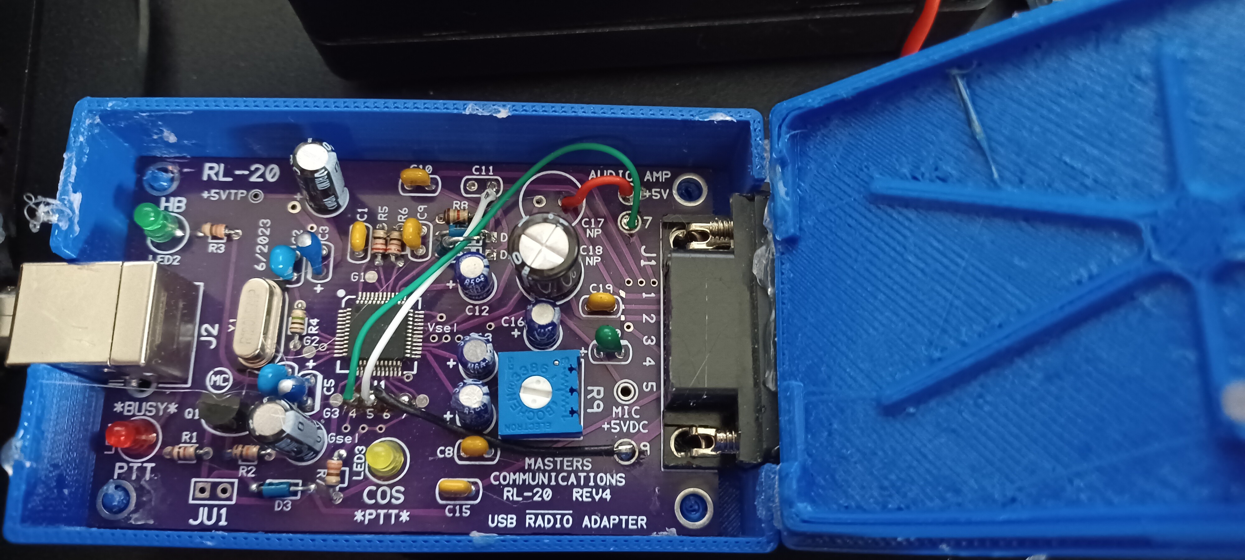
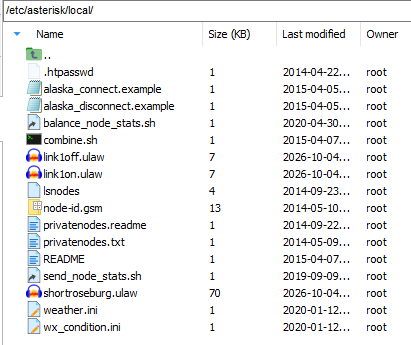
My node is 408670
Thank you very much to everyone for responding. I am very sorry for the very late response as this move has taken most of my time and at 76 years old my mind just doesn't respond like it used to. To explain the situation I have moved from So. Cal. to Topaz lake California where my Daughter has purchased lake side property and will soon have an RV park. I am building this node so I can send it to the group in So. Cal. And stay in contact. The best part is I now live in paradise with clean air and water.
Dale, N6ZCM, Here is where I stand:
I have followed your recommendations and now I have this:
Added to rpt.conf
[functions-main](!)
;;;;;;;;;;;;;;;;;;; functions stanza ;;;;;;;;;;;;;;;;;;;.
;;;;; Macro Commands ;;;;;
5 = macro
………
;**************************************************
;
; Added Gary 9/22/26 to allow channel switching CM300
;
9410=cop,61,GPIO4:0 ;Link 1 On UF4
9411=cop,61,GPIO4:1 ;Kink 1 Off UF4
9510=cop,61,GPIO5:0 ;Link 2 On UF5
9511=cop,61,GPIO5:1 ;Link 2 Off UF5
9610=cop,61,GPIO6:0 ;Link 3 On UF6
9611=cop,61,GPIO6:1 ;Link 3 Off UF6
9710=cop,61,GPIO7:0
9711=cop,61,GPIO7:1
;**************************************************
……………………………………….
; 961 = cop,61 ; Send Message to USB to control PIO pins (cop,61,GPIO1=0[,GPIO4=1].....)
; 962 = cop,62 ; Send Message to USB to control GPIO pins, quietly (cop,62,GPIO1=0[,GPIO4=1].....)
; 963 = cop,63 ; Send pre-configured APRStt notification (cop,63,CALL[,OVERLAYCHR])
; 964 = cop,64 ; Send pre-configured APRStt notification, quietly (cop,64,CALL[,OVERLAYCHR])
; 965 = cop,65 ; Send POCSAG page (equipped channel types only)
;*************************************************;
;
; Added Gary 9/22/26 for chaannel control ov CM300
;
1 = *81 *80# ; play time and voice ID
2 = *961 gpio0 = out0 P P *70 P P *722 P *961 gpio0 = out1 P P *722 #
91 = *9411 *9511 *9611 # ;All Links OFF
90 = *9410 *9510 *9610 # ;All Links ON
92 = *9511 *9611 # ;Link Port 2 and 3 Off
* NOTES 1 works, 2 works although 961 not defined, 90-92 just gives a series of beeps.
;*************************************************
………
Added to simpleusb.conf
gpio4=out,0 ;Link Port1
gpio5=out,0 ;Link Port2
gpio6=out,0 ;Link Port3
gpio7=out,0 ;Test LED
--------------- end of changes
With a scope I monitor gpio 4,5 and 6 and there is no change when I execute the macros. I don’t think the gpios need a pullup resistor or am I wrong here?
I am using ASL3 on all of my nodes. My next step is to rebuild this node with the older VoIP version. It just may not work with Version 3?
Thanks for patients with and old man. (licensed since 1965)
Scott I am looking at your boards, thanks