ASL USB Audio notes

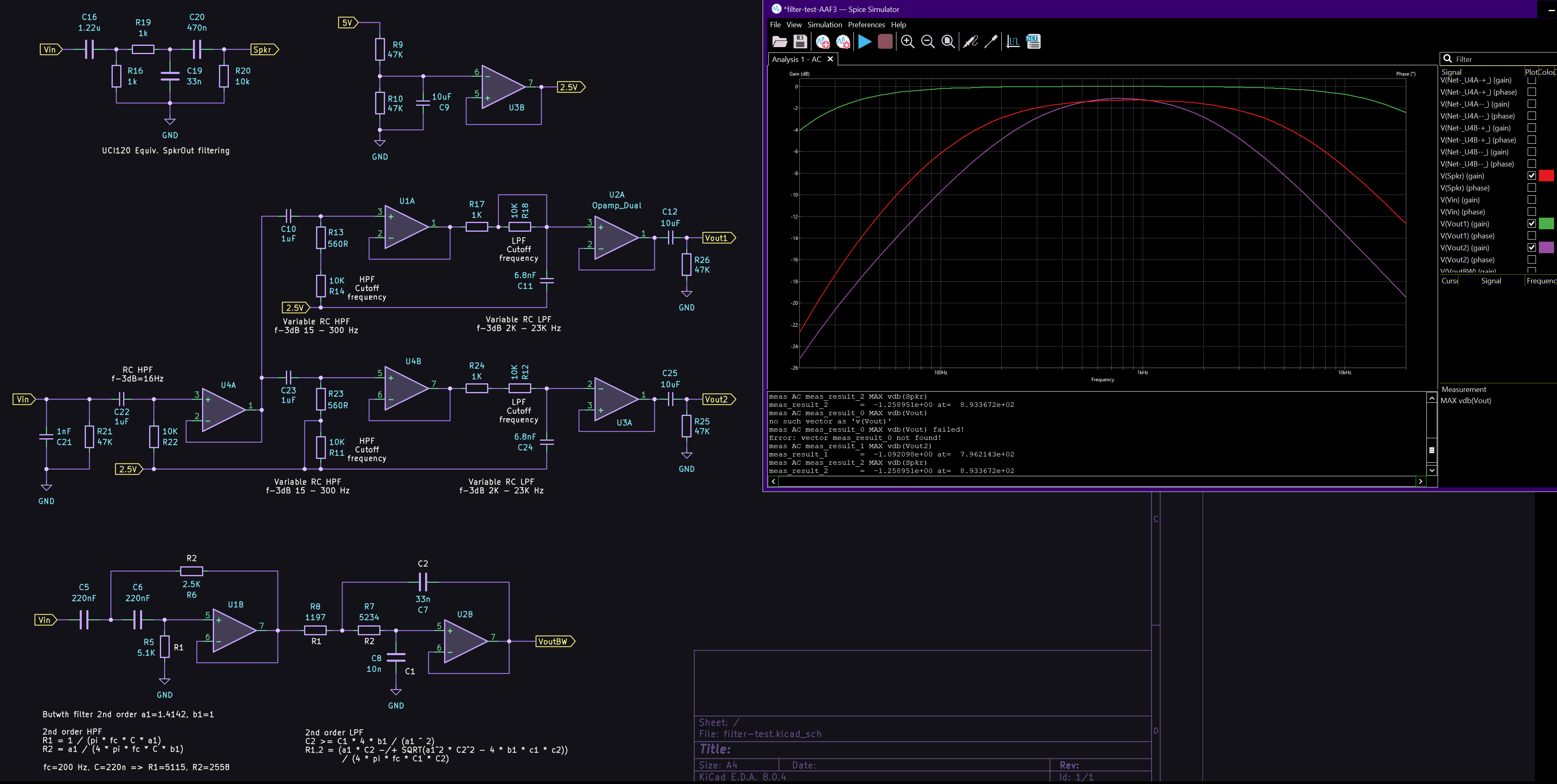
Having been looking closely at many aspects of audio within the app_rpt code, particularly with regards to ensuring more consistent levels (and no clipping/distortion) for all users, I am noticing some interesting things in the app_rpt code. I thought I would start documenting some things here as I investigate further.

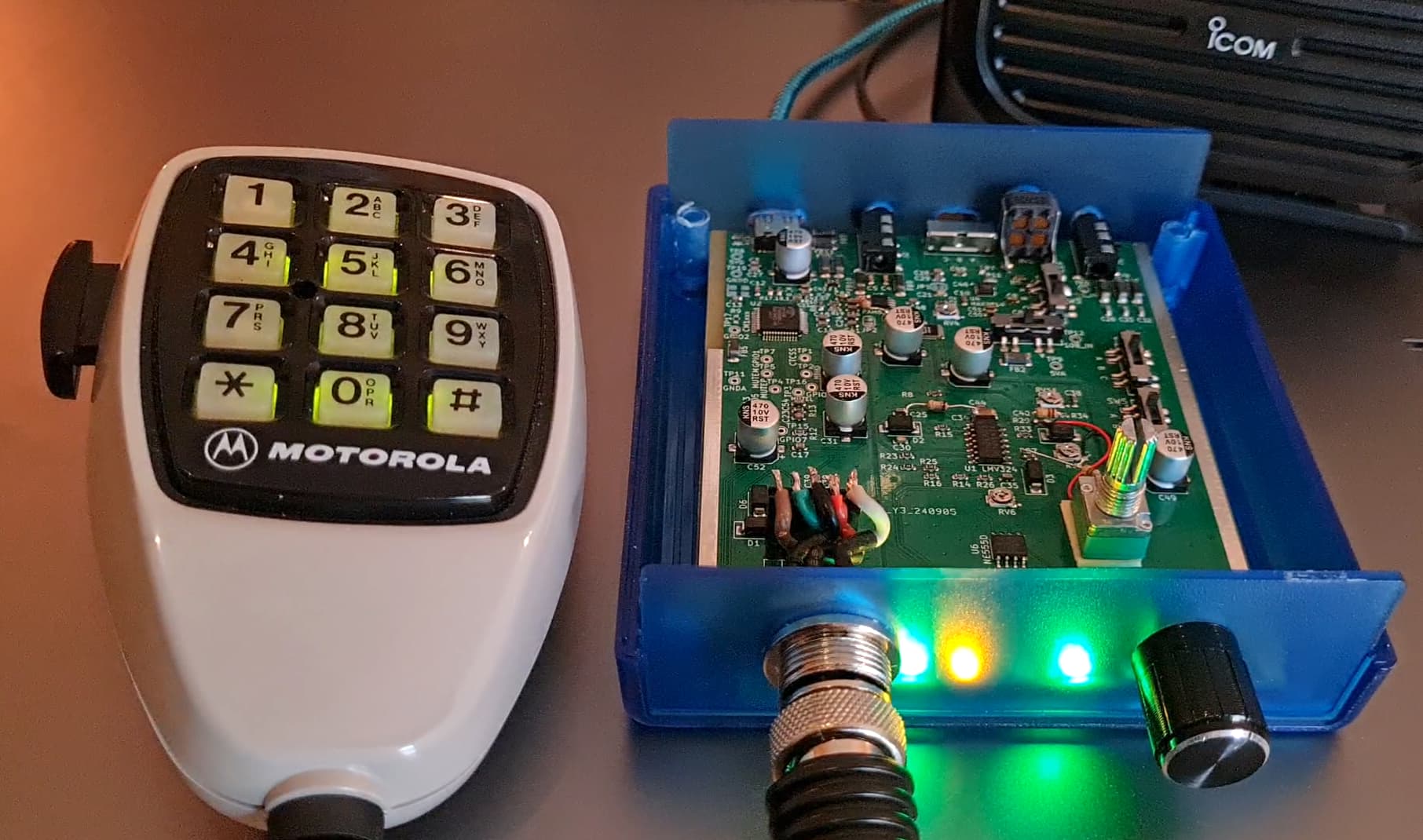
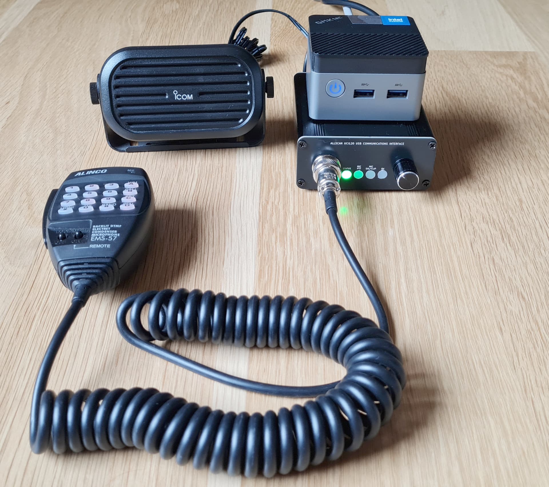
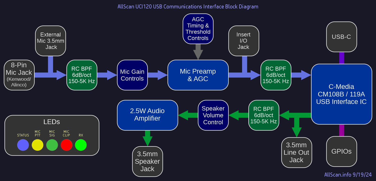
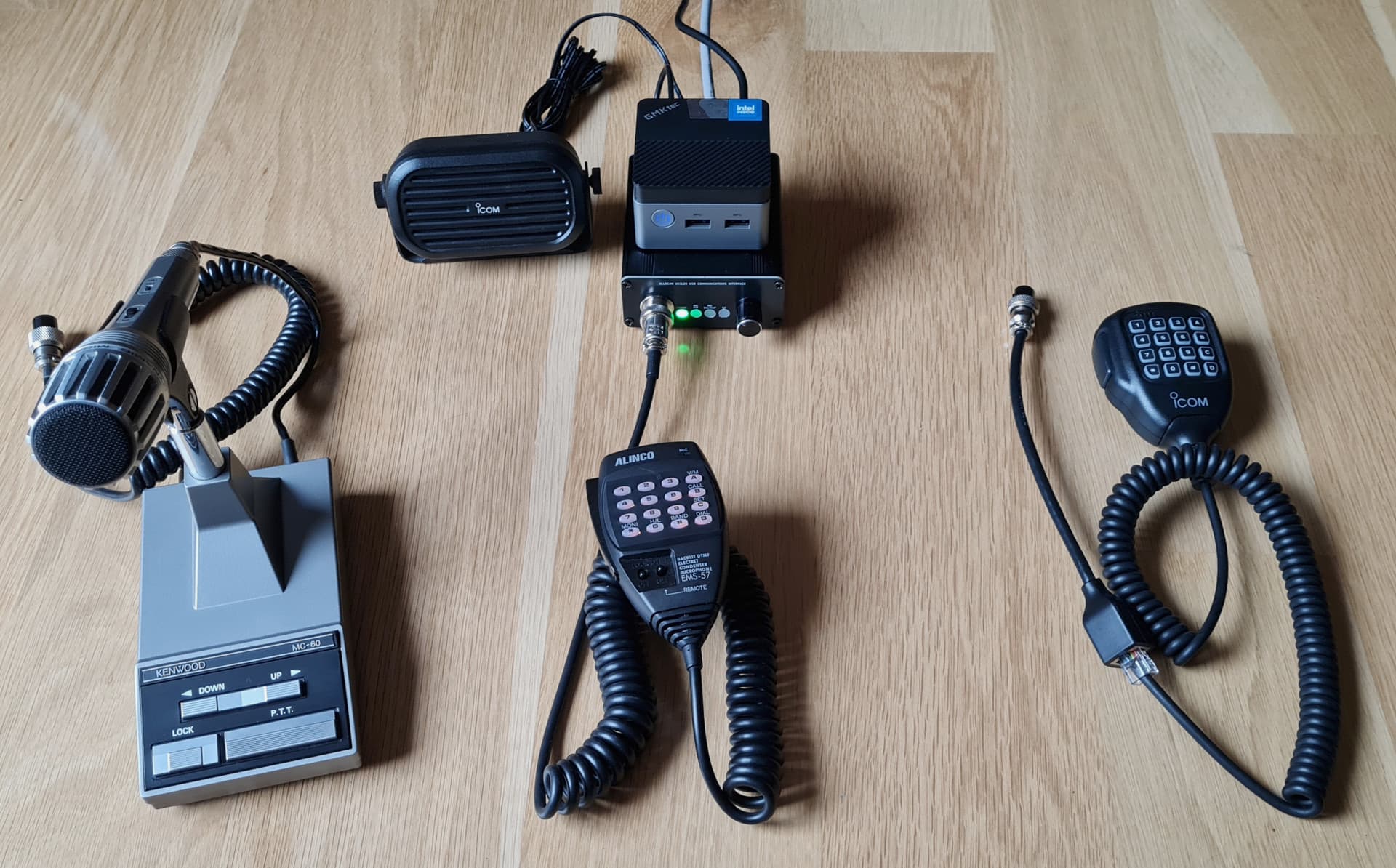
The first thing that should be noted is that pretty much all nodes I’m aware of use C-Media CM1xx ICs. This of course refers to real nodes - not phone or PC apps such as DVSM or iaxRpt. But in the class of real nodes, whether they be repeaters, Pi-hat (SA818) nodes, mobile radio nodes, or radio-less nodes, probably 99% of anything built in the past 10 years is using either a C-Media CM119A, CM108AH, CM108B or CM119B.

The CM1xx A/AH versions replaced the original (no suffix) CM108/119 ICs over 10 years ago, and those then went EOL according to C-Media several years ago to be replaced with the B suffix versions, which have significantly different specs, which no one I know of has yet fully characterized and confirmed through testing. (The A ICs are still available though, which is another story.)

The App_rpt code however essentially treats everything as a (15-year old) CM108/119, with a few twists. The original 108 and 119 were essentially identical, the only major difference (as far as ASL is concerned) being that the 119 has 4 more GPIOs.

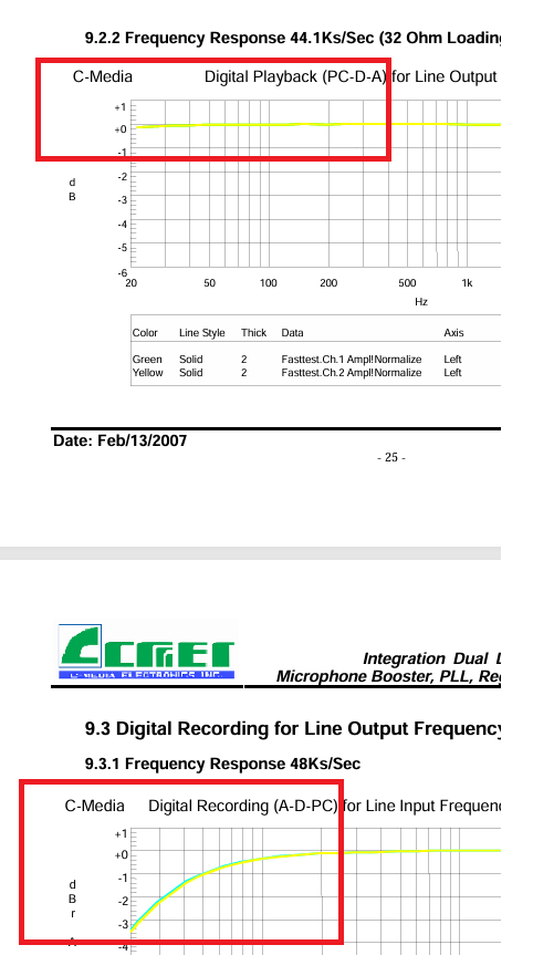
The A versions made some minor changes but from what I can tell the specs did not significantly change. The ADC on all 6 variants has an input range of 2.88Vpp. The DAC output ranges vary considerably however, as shown below:

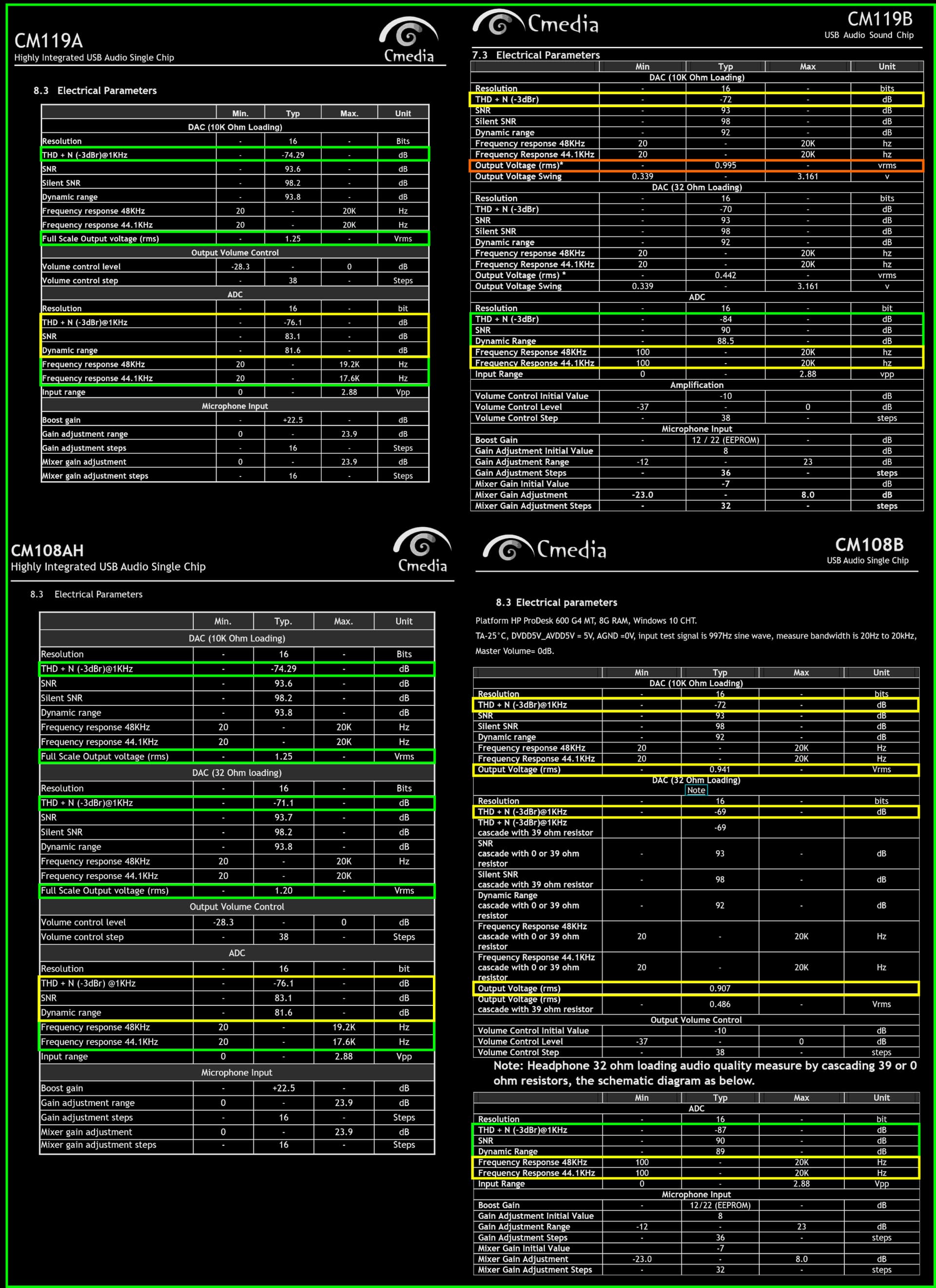
The changes in the B versions were much more significant. The crystal was removed, presumably with the internal PLL extracting 12MHz clock from the USB bus, but I was not able to confirm that with C-Media. The LF response is reduced by about 6dB < 100Hz. The ADC SNR and THD was significantly improved. And the gain settings are quite different:

ADC:
Orig: 0 - 22.5 dB range in 16 steps, with +20dB boost option
A/AH: 0 - 23.9 dB range in 16 steps, with +22.5dB boost option
B: -12 - 23 dB range in 36 steps, with 12 or 22 dB boost option

Which with boost off should translate to:
Orig: 0 - 22.5 dB range in 16 steps
A/AH: 0 - 23.9 dB range in 16 steps
B: 0 - 35 dB range in 36 steps

DAC:
Orig, A/AH: -45 - 0 dB range in 38 steps
B: -37 - 0 dB range in 38 steps

There are discrepancies on A&B datasheets between the gain ranges and steps shown on the block diagram vs. the specs tables. So the only way to confirm the above would be to test on an A & B version and confirm what actual voltages come out of the DAC for a full-scale input at various gain step settings, and similarly what happens with a known voltage on the ADC input with different gain settings.

Based on testing I’ve been doing on some ANR100 radio-less nodes, one with a CM108AH and the other with a CM108B, I notice the B needs significantly higher level settings. I use rxmix of 100 and txmix of 500 on the AH, but need rxmix of 750 and txmix of 800 on the B. (Both with rxboost=off). That’s a huge difference, particularly between 100 to 750 for rxmixset. I’m running about 1.4Vpp into ADC which should only need 6dB of boost to be at the ADC rated input range of 2.88Vpp. The specs above would imply the B has more gain in both directions than the A’s, but my measurements seem to show the opposite. The 108B DAC is rated at 941mVrms out vs. 1.25Vrms for the AH at 10KΩ but that’s only a 2.5dB difference.

A big question is are the B’s suitable for use in nodes and URIs. Their reduced ADC response below 100Hz could be an issue for apps using usbradio to CTCSS decode of lower PL tones, but that doesn’t apply to most small personal nodes or radio-less nodes. There has been speculation that the B’s might not have as good of clock/sample timing stability or temperature range but I’ve seen no confirmation of that. The lower gain of the B’s could be an issue in some apps but most apps don’t need a ton of gain and support for lower gains can be better in some cases. Lastly the B’s are widely available, in current production, and have 10dB better ADC noise specs.

The next variable is ASL itself, which has defines for all these variants, but really doesn’t do much differently between them, and has some clear inconsistencies. It looks like some efforts were made to put in some scaling for CM119B vs. A but the values are the same (1000) and thus no scaling is actually done (see C119B_ADJUSTMENT).

Then there is this bit of code in chan_simpleusb.c where it outputs audio to the USB interface:

				/* Adjust the audio level for CM119 A/B devices */
				if (o->devtype != C108_PRODUCT_ID) {
					register int v;

					sp = (short *) o->simpleusb_write_buf;
					for (i = 0; i < FRAME_SIZE; i++) {
						v = *sp;
						v += v >> 3;	/* add *.125 giving * 1.125 */
						v -= *sp >> 5;	/* subtract *.03125 giving * 1.09375 */
						if (v > 32765.0) {
							v = 32765.0;
						} else if (v < -32765.0) {
							v = -32765.0;
						}
						*sp++ = v;
					}
				}

And this in chan_usbradio.c where it reads USB audio:

/* Decrease the audio level for CM119 A/B devices */
if (o->devtype != C108_PRODUCT_ID) {
	register short *sp = (short *) (o->usbradio_read_buf + o->readpos);
	register float v;
	register int i;

	for (i = 0; i < res / 2; i++) {
		v = ((float) *sp) * 0.800;
		*sp++ = (int) v;
	}
}

And this where it writes USB audio:

/* For the CM108 adjust the audio level */
if (o->devtype != C108_PRODUCT_ID) {
	register short *sp = (short *) o->usbradio_write_buf;
	register float v;
	register int i;

	for (i = 0; i < sizeof(o->usbradio_write_buf) / 2; i++) {
		v = ((float) *sp) * 1.10;
		if (v > 32765.0) {
			v = 32765.0;
		} else if (v < -32765.0) {
			v = -32765.0;
		}
		*sp++ = (int) v;
	}
}

This above 3 code excerpts are all conditioned on != C108_PRODUCT_ID, which will always be true on any node made in at least the past 10 years. This appears to be a major issue that could result in perfectly good incoming IAX audio being digitally clipped before being output to the DAC. Usbradio is scaling all Tx audio going to the DAC by 110%, while at the same time attenuating all incoming audio by 20%, increasing the likelihood of digital clipping on Tx audio, wasting 20% of available dynamic range on incoming audio, and eating up CPU cycles to do floating point scaling on every sample, apparently as a hack to match levels to an IC that has been out of production for over 10 years. Simpleusb does pretty much the same thing but scaling in a more CPU efficient way to 109.375% on Tx audio but then not doing any scaling of Rx audio.

Update: Did some testing today with both simpleusb and usbradio drivers and confirmed these code sections above are completely unnecessary and should be removed asap. At that point there may be some significant work to properly characterize these various ICs and see if there might be a good way to get their gains to be more consistent by adjusting the mixer settings rather then by scaling the incoming and outgoing audio streams. Ideally the rx and tx mix settings could be in dBV instead of arbitrary (unitless) numbers, and ASL would then figure the exact mixer settings required to achieve those actual input and levels on each CM1xxx variant.

1 Like

Thank you.
We observed the inconsistencies but have not deciphered the issues like you.

I have often wondered why the C119 was the only practical way to do ASL?
I realize there are wide ranges of signals, perhaps requiring significant code variations. But as someone recently remarked, is it not possible to use other in/out? The suggestion as I recall was old laptops, etc.

The Raspberry Pi today is so much more powerful than the early machines. Just a thought. Is it possible to offload the processing from the CM119 to the Pi? Then the world is your oyster, as the old saying goes. There are myriad techniques on the Pi. Perhaps, just gives the hooks to the Pi and let others work with developing apps, boards, etc.

ASL3 is so fabulous compared to the first versions I used.

I appreciate all your effort and the team’s work on the fantastic new tool.

The CM1xxx ICs have useful features including an internal mixer and GPIOs and with the cost being only ~$2 there just hasn’t been much reason to support other ICs. The mixer does come in quite handy because you can adjust levels easily with no need to touch any hardware or trim pots. Audio chips/drivers could vary greatly between Pi 0/2/3/4/5/hats/etc., would not likely be of use on x64 platforms, and likely would not include GPIOs or mixers, thereby requiring use of a separate RPi GPIO driver and more inconsistency with x64. Also RPi stopped making sense as a platform years ago when their prices become double that of miniPC options that have more features and are almost as small. Maybe someday RPi prices will come back down to Earth or they will release a “Pi Zero 3” with more than 512MB (?!) of RAM, but until then there are numerous models of miniPC that work much better. So in summary it’s just simpler to plug in a $3 CM1xx fob into an RPi USB port than try to support inconsistent audio/GPIO HW.

Thanks. I appreciate your response.

I agree the fob for straight audio makes sense. I have a handful that I played wit. But the PTT function still requires a hack. That would be beneficial from another route, either a hardware or software solution from the computer / RPi. It could be a Pi Gpio pin ( like the early ASL parallel port) or the passing of a simple handshake code, such as setting one if the Vars.

Just thinking of ways to expand applicability, simply.

Appreciate all your work.

Just opened a bug report on the above mentioned issue - Simpleusb and Usbradio drivers are introducing digital clipping into all Tx audio · Issue #399 · AllStarLink/app_rpt · GitHub

Having been a EE and audio engineer for 30 years I am amazed that these hacks ever made it into the ASL code 10 years ago and that it went unnoticed until now. If anyone has any questions on this LMK.

In the meantime my UCI120 product is moving along well. Just got the first proto boards back and working 2 days ago. See the product page at AllScan - Products - AllScan UCI120 USB Communications Interface and a few quick demo videos: Link

Been looking for this for some time. excellent work.
Would you be making a board only (meaning populated board) option when you make this available?
what about price range?
Maybe a future dual node version?
Mike N3IDS

I have built 6 nodes in the past month and had to disable the Auto Gain Control using alsamixer and then store it using alsactl store. It was constantly changing levels.

I dont know if there is a better way to disable that but its stabilized my nodes.

Hi Mike, yes the UCI120 will be available as the assembled board without the enclosure and with the mic jack, LEDs and volume knob included but not soldered on. Should be ready to ship these in about 2 weeks. In your case you would not need the enclosure, but the back panel jacks and controls will be populated on the PCB so if you were going to mount inside some other enclosure such as a comms speaker or phone patch I would suggest have the back of the PCB mounted at the back or in such a way to make it easy to access the back of the board.

We are redoing the LEDs to be standard 5mm LEDs that will be on a separate small board, rather than LED diffusers and SMT LEDs as shown above. So the LEDs will end up looking more like this mockup:

The small LED and mic jack board will be able to easily mount anywhere.


And to N5ZR, how were you using alsamixer and AGC with ASL? I’ve only used Usbradio and Simpleusb drivers which talk direct to the CM1xx and don’t have anything to do with alsa. Is the AGC function you’re referring to part of Linux Alsa package? Have you tried the Asterisk AGC function?

How did AGC happen in the first place? I’ve never encountered that on any system ever.

Alsa is installed on the appliance. Maybe you don’t build those? Does not negate the fact that its there and not “muted”.

Well it seems to come back(unmute) after changes in radio-tune and simpleusb-tune so my efforts are for not.

Never mind then.

Is there room to squeeze a rasp zero 2 in there? maybe an ethernet adapt… might have to put on an external antenna for wifi
really looks professional!!
I’m like a kid just before christmas.
Mike

If the Pi Alsa driver is interfering with ASLs use of the CM1xx IC I would suggest maybe uninstalling Alsa, or opening a bug report on the app-rpt github page.

You could probably fit a Pi Zero 2 in the enclosure but I would definitely not recommend it for a number reasons: no ventilation, wifi signals would be blocked, you’d have to add notches in the back panel for the power/ethernet/usb cables, a layer of insulation would have to be added to prevent shorting anything on the PCBs, Pi’s have no power switch or easy way to do a controlled shutdown, EMI/RFI could be introduced inside the enclosure, and last but not least I don’t see how a Pi zero 2 with only 512MB RAM can be a reliable long-term ASL3 platform ie. without going into disk swap and trashing the SDCard after not too long (if someone can explain technically how that wouldn’t be an issue I’d like to hear it).
BTW I ordered a miniPC for evaluation yesterday that is only 3" x 3" x 1.75" which should complement the size of the UCI120 very well, and it’s about 50 times more powerful than a Pi Zero - https://www.amazon.com/dp/B0B75PT2RY

something bothers me.

The THD +N is improved and the SNR is improved,
but the low cut goes from 20Hz to 100 Hz…

I WONDER IF THIS IS JUST SPECSMANSHIP. In other words, specs aren’t actually better, they just gamed the TEST measurement conditions by cutting out 6dB of grunge, 1/f noise and 60Hz hum.

I Looked at my 2007 edition of the CM108 original PDF cut sheet and the early version ADC AudioPrecision graph has a noticieable roll off vs the DAC output… EDIT: Oh LOOK, just took a peek at the CM119b 2013 PDF and there’s NO Ap performance plots…

.
SIGNAL CONDITIONING:

It only bothers me a little bit that these DACs have no signal conditioning (at least the URI include a very significant Low Pass Filter.:, about 3.5kHz 3dB point. I think the only pet peeve is there should be a 100k resistor to ground the floated end of the C18 electrolytic coupling cap (in case the radio TX port has a Vcc mid supply of say 6V, the thing would get reverse biased.)

Dave you mentioned some experience in audio stuff. This one little resistor will get rid of much of the POP click on a guitar DI box by draining that floating input cap DC bias. Its sort of always overlooked

The other curious fact. The mic circuit has foldback/comfort sound to the AF out. You could theoretically just pass receiver audio straight to the AF out completely in the analog domain. Or muck it up and have an echo…

In my experience both the CM1xx A/AH and B’s are CD-quality as far as in standard use as an audio interface with proper layout, analog and digital power supply separation and filtering. If you start connecting them to radios or have Watts of transmitted RF very close by without proper RFI filtering then it becomes more challenging but these are overall very good sounding interface ICs. (Definitely better than the AIOC chips which have only a 12-bit ADC and DAC.) The B does have about 6dB reduced ADC response < 100Hz, so for use with a repeater using PL’s < 100Hz I would use a CM119A, but otherwise the slightly reduced LF response is helpful because you already need to bandpass the Rx audio to make best use of the ADC dynamic range, reduce pops, thumps, road/wind noise, etc. As for the DAC, ASL upsamples to 48KHz and there could be some slight noise up around 20KHz since this is a $2 IC but I’ve never heard it and a URI/UCI will usually have some LPF there (a 150-5K Hz BPF in the case of UCI120), and in most nodes that’s then going into a comms speaker (with very little response above 5KHz) or a standard radio input with very sharp BPFs. A repeater system is a different story and you’d then probably look at some steeper filtering before going direct into an FM modulator, but that’s not my interest as far as product development. The market for personal nodes is 100x that of repeater systems and people have already been doing repeater systems just fine for many years.

Electrolytic caps and 100K resistors aren’t an issue in any URI/UCI stuff I’m doing, in the case of the UCI120 the CM1xx DAC output goes to 1.22uF of (nonpolarized) multi-layer ceramic caps and then to a 1KΩ volume control which together form a 150Hz HPF ahead of the audio amp to reduce any residual PL tones or LF noise that the occasional ASL user sends over IAX. (Only time you need an electrolytic cap is if you’re driving a very low-Z load like a speaker and need full 20 - 20K Hz response. Also electrolytics are now rarely used for values <= 100uF.) The UCI uses electrolytics only for power supply filtering and on the Line/Headphone Out, since the CM1xx will drive 32Ω headphone loads. The Speaker out jack does not need electrolytics anywhere as it’s a bridge output configuration, which is really the only way to go for a simple radio-less node running off of 5V USB power. I might at some point add some step-up converters, +/-12V internal rails and a class AB audio amp but that would increase cost a bit.

The CM1xx does indeed have an internal mixer allowing Rx audio to be mixed into Tx audio with zero latency and in analog. This would only be used in repeater applications however, there’s no need for it in a personal node.

BTW did a quick demo video yesterday of the UCI120 with a few different mics: https://youtu.be/GSzhcmRld3A The GMKtek NucBox5 MiniPC works great, very powerful yet ridiculously small. Loaded Deb12 and ASL3 super quick and easy as could be.

1 Like

Dave, this is impressive work. Imagine trying this w/o Eagle/KiCAD/china prototype board fab.

I want to look at that MAX9814 chip AGC. I’ve had some issues with the Plantronix CA12CD headset interfacing. It’s easy to set levels on the unit, but when you have multiple operators the mic level is unpredictable. Years ago I kluged a Leveling Amp FET shunt circuit w/ a dual op amp pkg & a BJT, but the result wasn’t as smooth as I’d like.

also like the provision of an INSERT jack, for the discerning Op who wants to run the signal thru his tube EQ or fender twin reverb (or even just patch to a scope or digipan for the waterfall.)

that TP18 in the schematic doesn’t have a defined DC value if jp4 is open (ok, depends on cap leakage). In LT-spice the engine would bark there’s no DC path to ground. Of course the only problem is if someone patches into an EFX/micpre box with P48 and backfeeds the unit.

Found this discussion about the chip and pin 15 (underpad supposed to be grounded, but they left it ambiguous). The eval board is $75 but there’s cheaper boards on EBAY for around $5, so maybe I’ll grab one of those to play with. (also gotta grab me one of those tiny PC’s :slight_smile:

KD6OVS

The 2nd proto run of 10 UCI120s is now out for delivery with UPS so should have those very soon. The MAX9814’s have always worked perfectly for me, far better than some other IC options such as SSM2166/67. It does have the underpad + 3 ground pins (which are all properly grounded and reflow soldered on our boards), I suppose because the pkg is ridiculously small, but it’s packaged not unlike a 3W audio amp IC yet is using only a few mA, so that does seem like overkill. Definitely wouldn’t try hand soldering one.

Good point on the TP18 location next to the Insert I/O jack, which has 3 coupling and 2 bypass caps and ferrite beads but no resistor. I have added a 47K there on the sch. I had also made a few minor optimizations to the level detector circuit that’s also driven from that point.

I’ve done a good amount of analog design over the years but had not actually done a PCB layout, G1LRO did that for the UCI120, and while waiting for the new boards to arrive I decided to do a small accessory board on my own to test a new potential fully Class AB audio amp IC, try out some sweepable filters, and test some optimizations to the signal level LED circuitry. I was going to do just a small PCB module but then ended up going with the same form factor as the UCI120, thereby creating a matching accessory box that connects with a single 3.5mm aux cable, adds a 2nd speaker output, signal LED for the Spkr audio, and sweepable filters (variable 15-300 Hz HPF & 2-23K LPF). Finished the schematic and board layout in about 2-3 days work. Should have some of these boards in the next week or so.

The UCI120 is quite nice as a MAX9814 eval board even if you didn’t use the USB audio I/O. All the MAX9814 AGC option pins can be configured, which is not possible on the small modules, and the Insert I/O gives you a direct out.

There isn’t really room on the UCI120 enclosure panels to add the sweepable filter controls or the (internal DIP switch) AGC controls but I plan to do a larger version of the UCI120 at some point that brings all this out to the panels. Sweepable filters are not as useful on ASL as on HF but the parts cost to add them is around the $1-2 range, so there you go, and, it could have a switchable Aux In that would allow you to route an HF radio into audio path if you wanted to. I can now easily do many other similar concepts, such as something with a MAX9814, variable hi & low cut filters, and a variety of I/O jacks ie. basically a UCI120 + AAF3 but without the CM1xx. Below is simulation of the AAF3 frequency response at filters full open vs. closed, compared to the UCI120 speaker audio (fixed) response in red.

These are only 6dB/octave which keeps it very simple and inexpensive, but for a few $ more could support dual gang pots and 12dB/oct filters, though the design starts to get considerably more complex there if you want higher-order and variable optimized filter slopes eg. Butterworth response. At that point it might be more cost-effective and simpler to patch in some audio dynamics/EQ plugins into ASL. LADSPA/LV2 plugins could probably be patched into one of the channel drivers in a couple days work eg. Linux Studio Plugins Project

Had some time to look further into another ASL code rabbithole today relating to the SimpleUSB channel driver that will introduce clipping into nearly all Rx audio: In chan_simpleusb.c::simpleusb_read()

	/* scale and clip values */
	if (o->rxvoiceadj > 1.0) {	
		...
		for (i = 0; i < f->samples; i++) {
			f1 = (float) p[i] * o->rxvoiceadj;
			...
			}
	}

With the comment stating “scale and clip values”, it only follows that the code would do exactly that. To be clear, audio should never be clipped, not in ASL, Asterisk, or any application for any reason. There is no possible benefit to clipping audio and doing so will result in reduced audio quality for all ASL users. The rx/tx mixer settings already enable users to adjust audio levels to within +/-1dB as needed. The issue report goes into significant additional detail - Simpleusb and Usbradio drivers are introducing digital clipping into all Tx audio · Issue #399 · AllStarLink/app_rpt · GitHub

In the process of figuring out exactly what this code was doing I added debug log messages of all the exact settings values sent to and from the CM1xx IC, and tested on both AH and B ICs. CM1xx ICs have a stated ADC input range of 2.88Vpp = 6.18 dBV, CM1xxB then supports adjusting that between -30 to 6 dBV in 1dB steps, and CM1xxA/AH supports -18 to 6 dBV in 1.5dB steps. These are just the stated specs, and there are some things that I still need to confirm with actual measurements, but what’s clear for now is that to avoid clipping and quantization errors being caused by the above code (until a fix is released in ASL) use an rxmix setting that’s an even multiple of (1000/16 = 62.5 x 2 = 125) for CM1xxA/AH or (1000/36 = 27 7/9 x 9 = 250) for CM1xxB.