Ok i have read it 4x now where would i put the pot in on your digram and what value would you think the pot should be.im looking for thr scmitics for thr uv5r if i need further help i will text you thanks for the info…
···
On Thu, Sep 10, 2020, 16:20 Pierre Martel via AllStarLink Discussion Groups <noreply@community.allstarlink.org> wrote:
| Pierre_Martel
September 10 |
- | - |
Ok now I Get it. Sorry for the delay in response.
The uv5r need to send the 1750 hz burst to open the repeater. to do this it need to have the PTT and band button pressed at the same time.
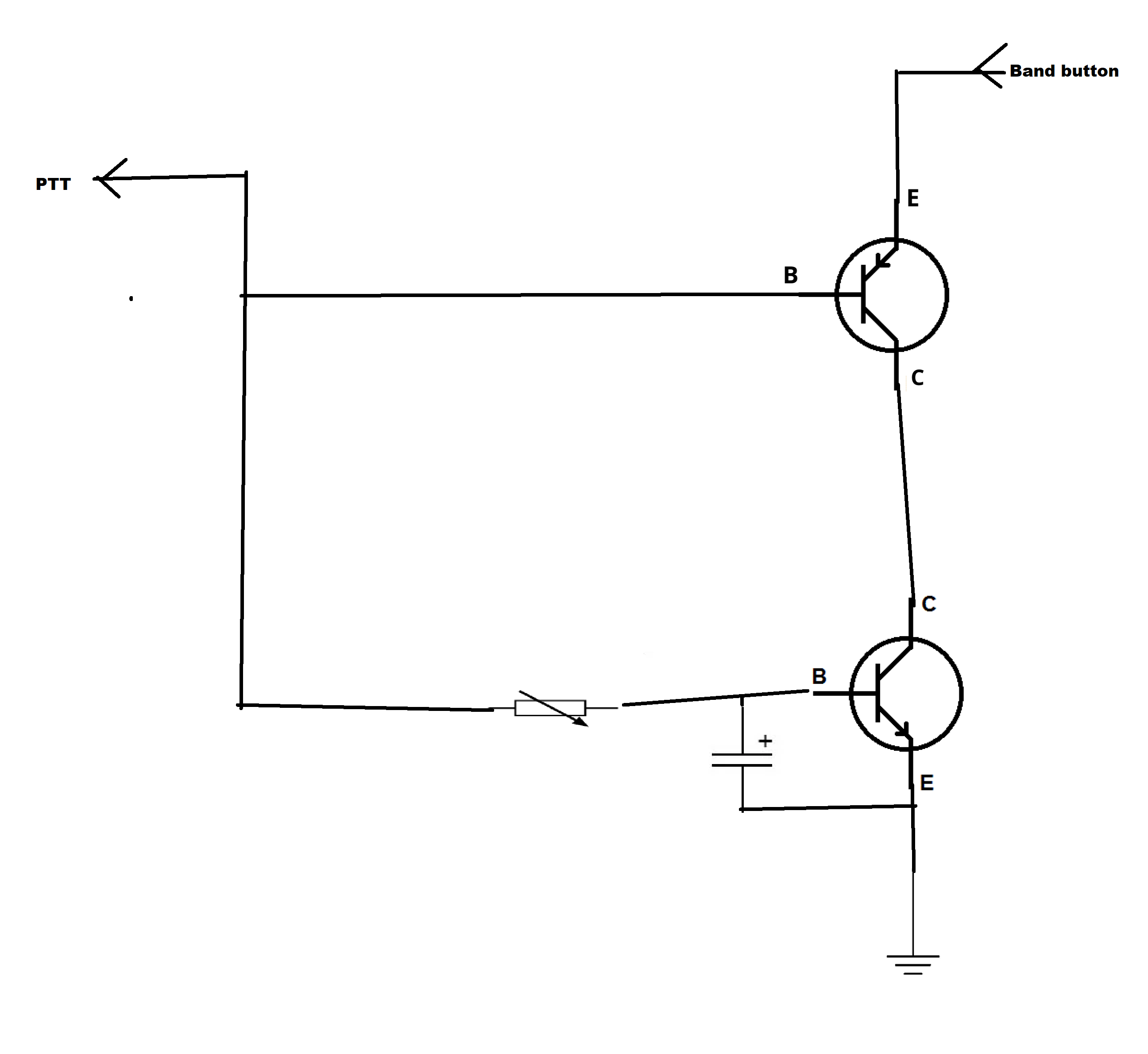
what I would do is that I would take a npn and pnp transistor a resistor and a capacitor and use them to drive the band button temporary at every ptt from the node. like the schematic I just did.
the transistor dont need to be high power, something like a 2N2222 for the NPN and a 2N2907 for the PNP
The way the circuit works. the ptt line is help high when not in TX this bring the NPN transistor in conduction but will also put the PNP transistor in saturation so there is no path for the band button current to flow to. at the same time the capacitor will be charged by the variable resistor.
when the PTT is grounded the PNP transistor enter conduction. and the NPN transistor is kept in conduction till the capacitor discharge into the variable resistor that is now held to ground. this make a path for the current from the band key to flow in both transistor. creating the 1750HZ tone briefly.
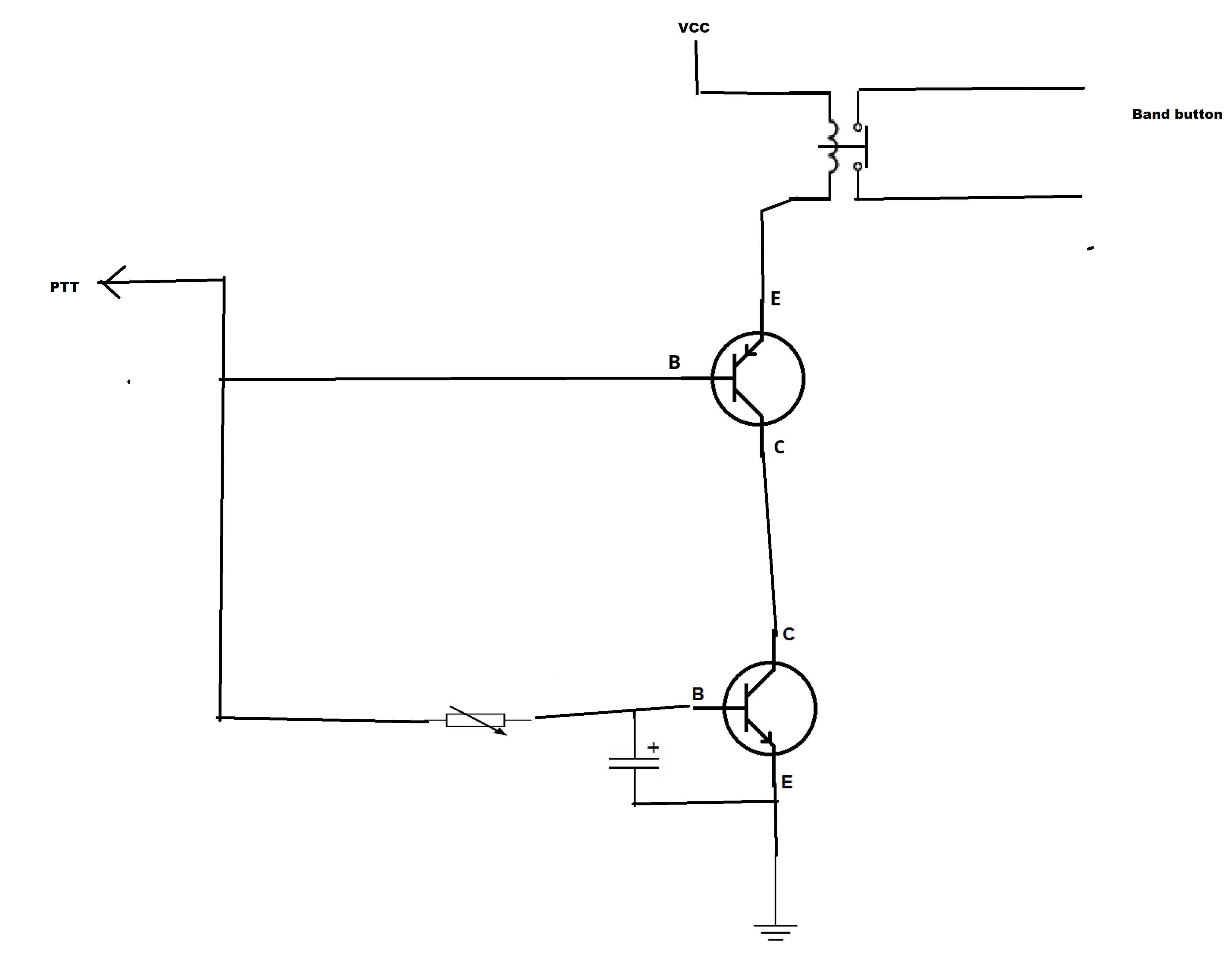
This is if the band button need to be put to ground for it to work. I dont know as I dont have a UV5R nor do I have the shematic. if it is not the case, and it need a short between the 2 pad of the button, I would recommand to use a small normaly open reed relay that would be connected to your positive power supply on a side of the coil and the other side of the coil to where I wrote band button on the shematic and use the switch of the relay to short the band button momentarily
as in this diagram
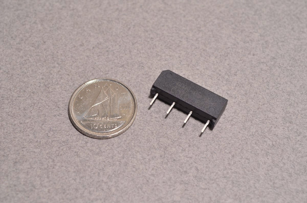
this is a 5 volt normaly open read relay.
as you can see it is not very big.
The lenght of time the 1750 hz tone is created can be calculated by the formula T= RC
R is in ohms and C is in Farad. in case of a 1uF and a 1 kiloohm resistor we would have 0.001 second delay. (wich is too fast for the circuit to be effective. )Now you need to play with the value to find what you need. Most repeater will react within 500ms to a 1750hz tone burst. so a 5uf with a 100k would do the job. use a small pot to lower the time if needed.
you can go read about the RC time constant here…
RC time constant
The RC time constant, also called tau, the time constant (in seconds) of an RC circuit, is equal to the product of the circuit resistance (in ohms) and the circuit capacitance (in farads), i.e. It is the time required to charge the capacitor, through the resistor, from an initial charge voltage of zero to approximately 63.2% of the value of an applied DC voltage, or to discharge the capacitor through the same resistor to approximately 36.8% of its initial charge voltage. (These values are deriv…
a very good read.
Pierre
VE2PF
Visit Topic or reply to this email to respond.
In Reply To
| ki7hub
September 4 |
- | - |
Rpi 3b, allstar /asterisk, rim lite sound interface, uv5r, now all i need is to get the asterisk system to generate the 1750Hz tone to wakeup the repeatwr that is not on site has no pltones and no intwrnet yes ican hit the repeater fron remote site where i have internet. Need scriot for asterisk to …
Visit Topic or reply to this email to respond.
To unsubscribe from these emails, click here.
